Electronics
Source: SPROUT_Design/Electronics
The Electronics directory contains the custom Arduino shield PCB that
interfaces the Arduino Uno Rev3 with the motor driver, QB3 pressure
regulators, solenoid valve, LCD screen, and the compute box’s power rails (see
Wiring for the full pinout).
Table of contents
Arduino shield
Source: Electronics/Arduino Shield
Designed in KiCad. The project targets an Arduino Uno Rev3 shield footprint and breaks out the following interfaces referenced throughout the wiring guide:
- Motor driver power and control (
M_DRV_PWR,M_DRV_ARD,M_5V) - Solenoid valve output
- 15 V actuator/regulator rails (
M_15V,R_15V) - QB3 pressure regulator channels (Chamber, Actuator 1–3)
- I²C breakout for the LCD display
3D preview
Board layout
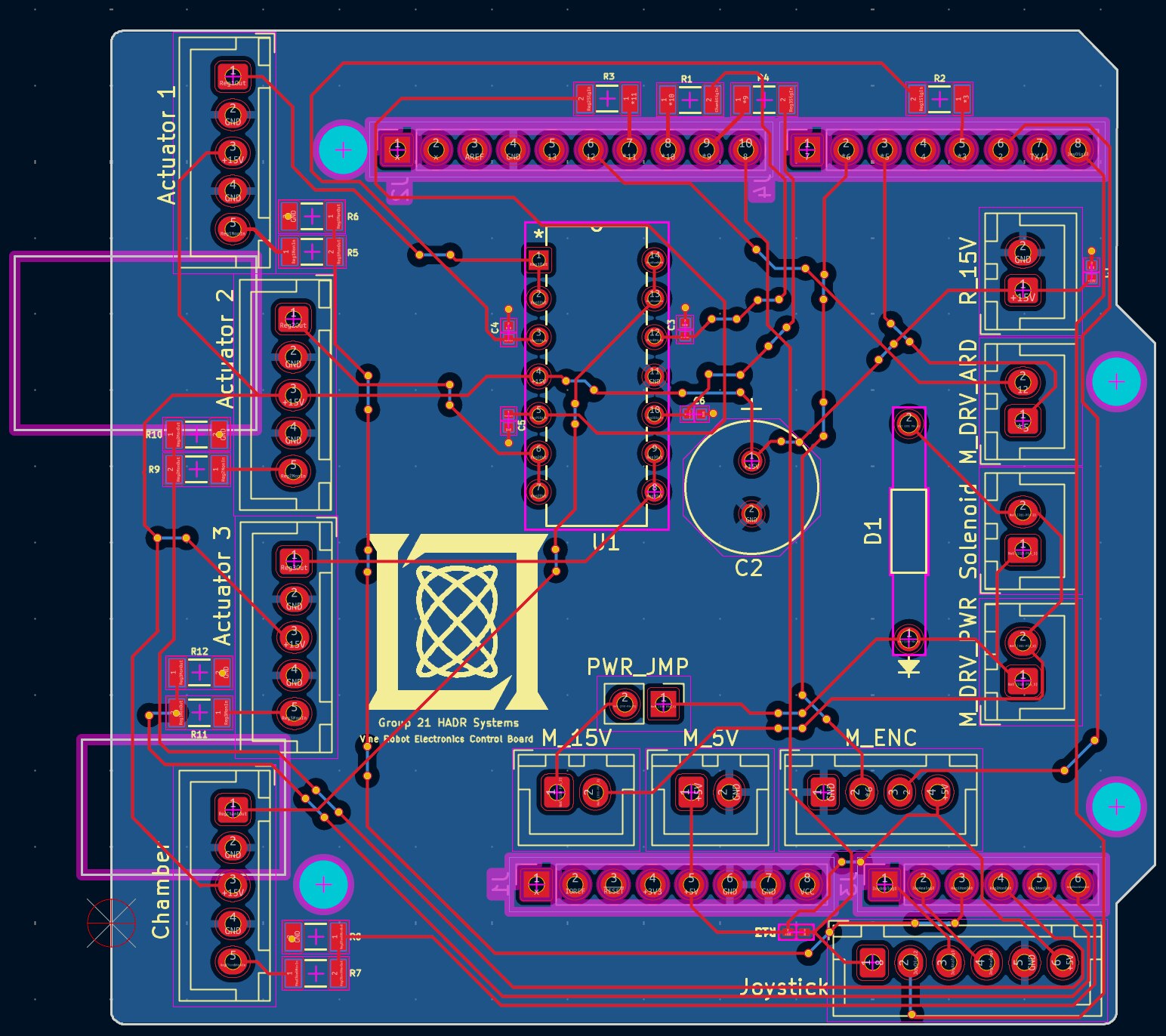
Figure 1. PCB layout showing traces and connector pinouts for the actuator, solenoid, motor driver, power, encoder, and joystick headers referenced in the wiring guide.
| File | Description |
|---|---|
vine_robot_arduino_shield.kicad_sch |
KiCad schematic |
vine_robot_arduino_shield.kicad_pcb |
KiCad PCB layout |
vine_robot_arduino_shield.kicad_pro |
KiCad project file |
vine_robot_arduino_shield.step |
3D STEP model of the assembled board |
v2_gerbers_8_23_2/ |
Fabrication-ready Gerber/drill files (rev. 8/23, v2) |
Arduino_MountingHole.pretty/ |
Custom KiCad footprint library: standard Arduino mounting holes |
Arduino_MountingHole_3.2mm.pretty/ |
Custom KiCad footprint library: 3.2 mm mounting holes |
To fabricate a board, download the contents of the v2_gerbers_8_23_2 folder (or
the corresponding .zip) and submit it directly to your PCB manufacturer of
choice.
To open and edit the design, clone the repository and open
vine_robot_arduino_shield.kicad_pro in KiCad 7 or
later — the custom footprint libraries in this folder are referenced by the
project’s local fp-lib-table and will resolve automatically.
Related hardware
The shield is mounted alongside the Arduino Uno Rev3 in the compute box — see Assembly → Step 3 for installation and Wiring for the full connector pinout. CAD for the shield’s mechanical footprint and mounting is included in CAD → Compute Box.