Enclosure Preparation and Mounting Layout
This page describes the preparation and mounting layout of the compute box enclosure used in the SPROUT robotic platform. The enclosure integrates compute hardware, power electronics, communication interfaces, and electropneumatic control hardware while maintaining portability and environmental protection.
The mounting architecture was designed to:
- preserve enclosure waterproofing
- minimize permanent enclosure modification
- support modular servicing
- allow repeatable assembly
Table of contents
- Primary components
- Provided CAD files
- General enclosure preparation
- Internal mounting system
- External robot mounting system
- Screen mounting assembly
Primary components
| Component | Manufacturer/Source | Link |
|---|---|---|
| NANUK 930 Empty Case | NANUK | Link |
| ABS Mounting Plate for Junction Box | Amazon | Link |
The ABS mounting plate serves as the primary internal mounting surface for compute hardware, power electronics, and electropneumatics.
Provided CAD files
STL files and CAD assemblies for all mounting components are provided in CAD → Compute Box.
General enclosure preparation
Prior to any mounting or adhesive bonding operations, the enclosure interior should be cleaned thoroughly.
Recommended procedure:
- Remove all foam inserts and debris from the enclosure.
- Wipe internal surfaces using isopropyl alcohol (IPA).
- Allow all surfaces to dry completely before proceeding.
Before adhesive bonding, all bonding regions should be lightly roughened using sandpaper and cleaned again using IPA.
Internal mounting system
Mounting plate design
Custom corner brackets were designed to secure the ABS mounting plate to the enclosure interior. These brackets are custom 3D printed and conform directly to the interior geometry of the NANUK 930 enclosure.
To ensure accurate fitment, the enclosure interior surface CAD model was obtained from the manufacturer and imported into SolidWorks. The mounting brackets were designed directly against the enclosure geometry to maximize bonding area, maintain mounting plate alignment, and minimize internal stress during assembly.
Each corner bracket contains M5 heat-set threaded inserts that interface directly with the ABS mounting plate hardware. STL files for all mounting components are provided in the CAD section. Install the heat-set inserts to the brackets before adhering them to the case.
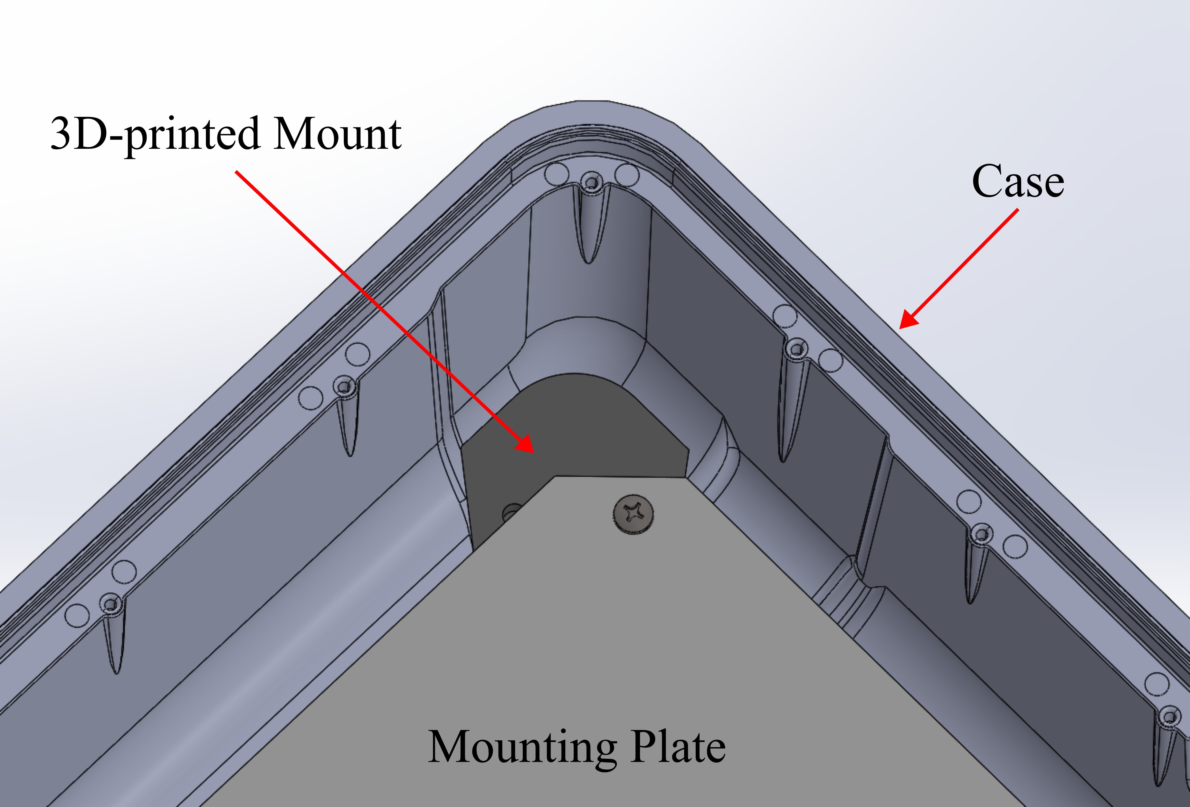
Figure 1. Internal corner mounting brackets used to secure the mounting plate.
Bonding procedure
The corner mounting brackets are permanently attached to the enclosure using two-part clear epoxy.
Recommended procedure:
- Prepare epoxy according to manufacturer instructions.
- Apply epoxy evenly to the bonding surfaces of each corner bracket.
- Position the bracket within the enclosure corners.
- Verify mounting plate alignment before curing.
- Allow full adhesive cure prior to mechanical loading.
Do not mount hardware to the brackets or subject them to load until the epoxy has fully cured — loading them early can weaken the bond permanently.
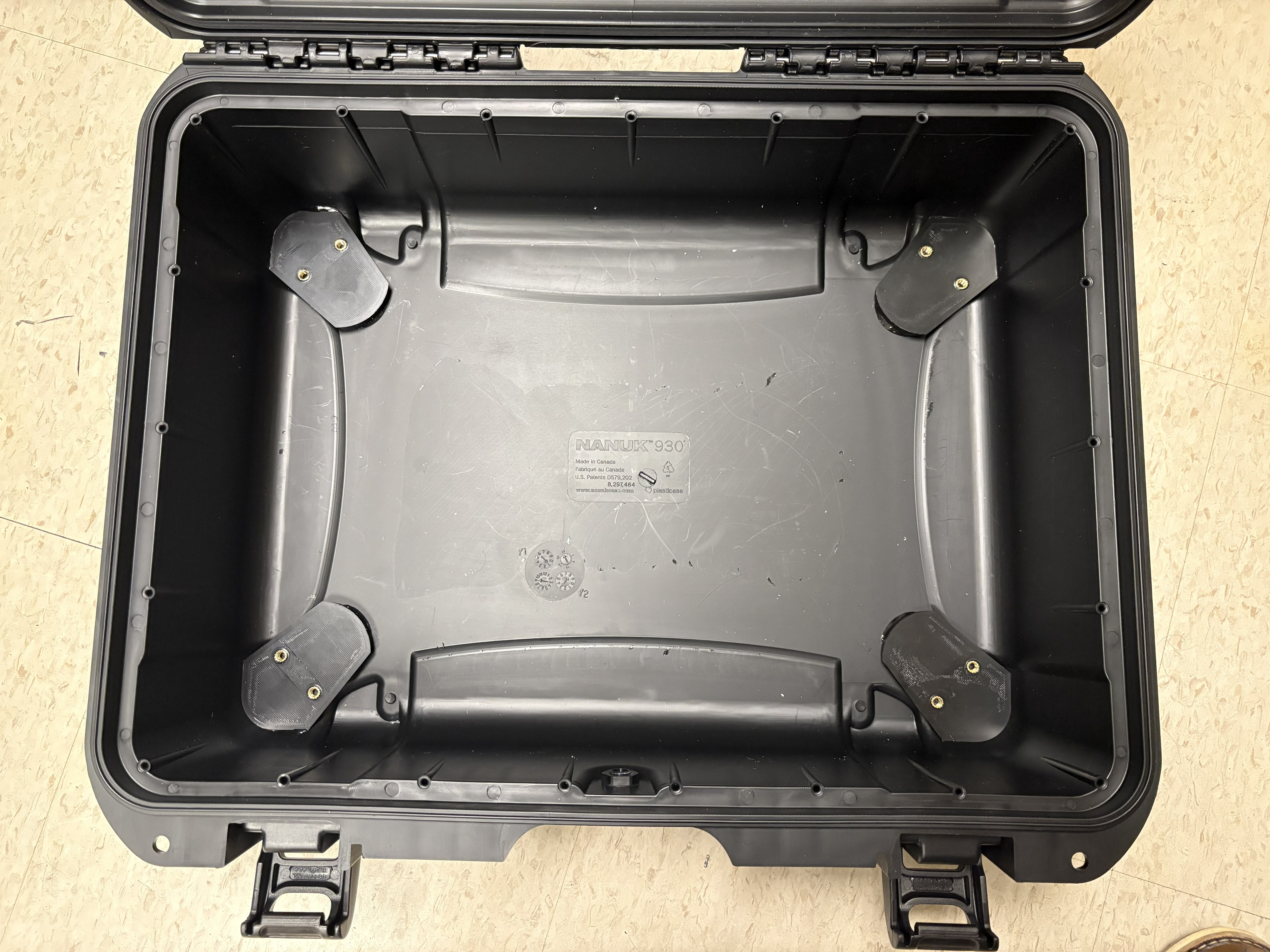
Figure 2. Epoxied internal mounting brackets with integrated heat-set inserts.
Top interface plate mounts
Additional custom 3D printed brackets are used to support the top acrylic interface plate. These mounting brackets were designed using the same enclosure interior CAD geometry and use the same epoxy bonding procedure described previously. There are 4 of these brackets, one for each corner.
The brackets contain M5 heat-set threaded inserts and support the acrylic interface plate used for external connectors, display hardware, user interface peripherals, and power switches.
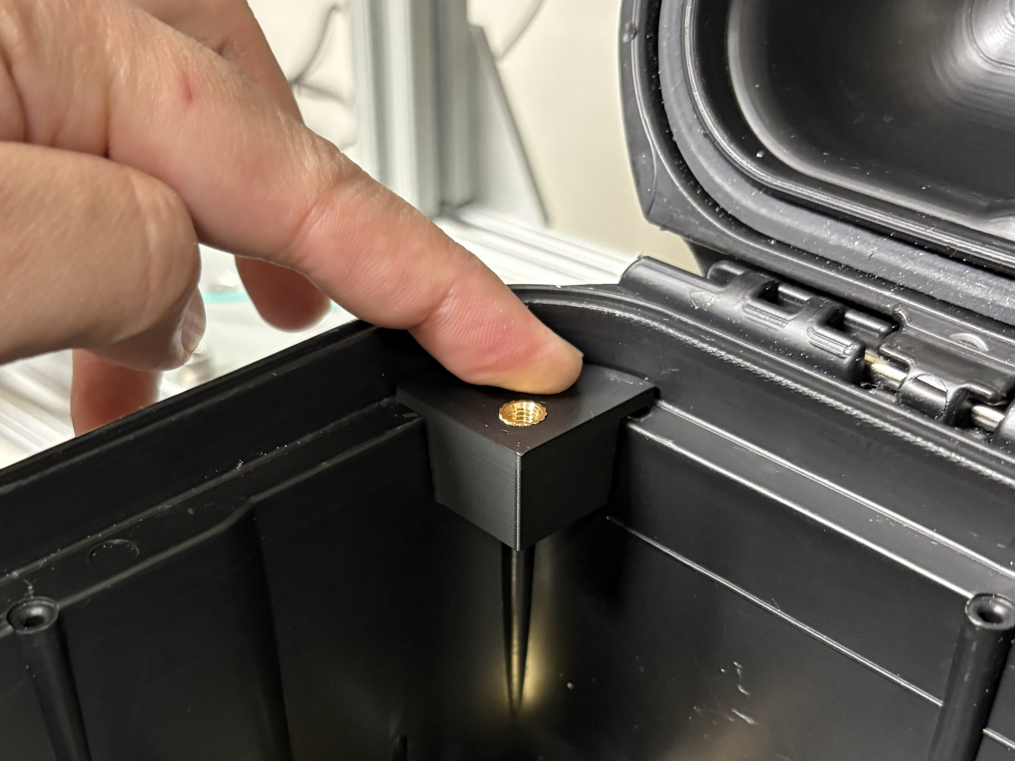
Figure 3. Top interface plate mounting system.
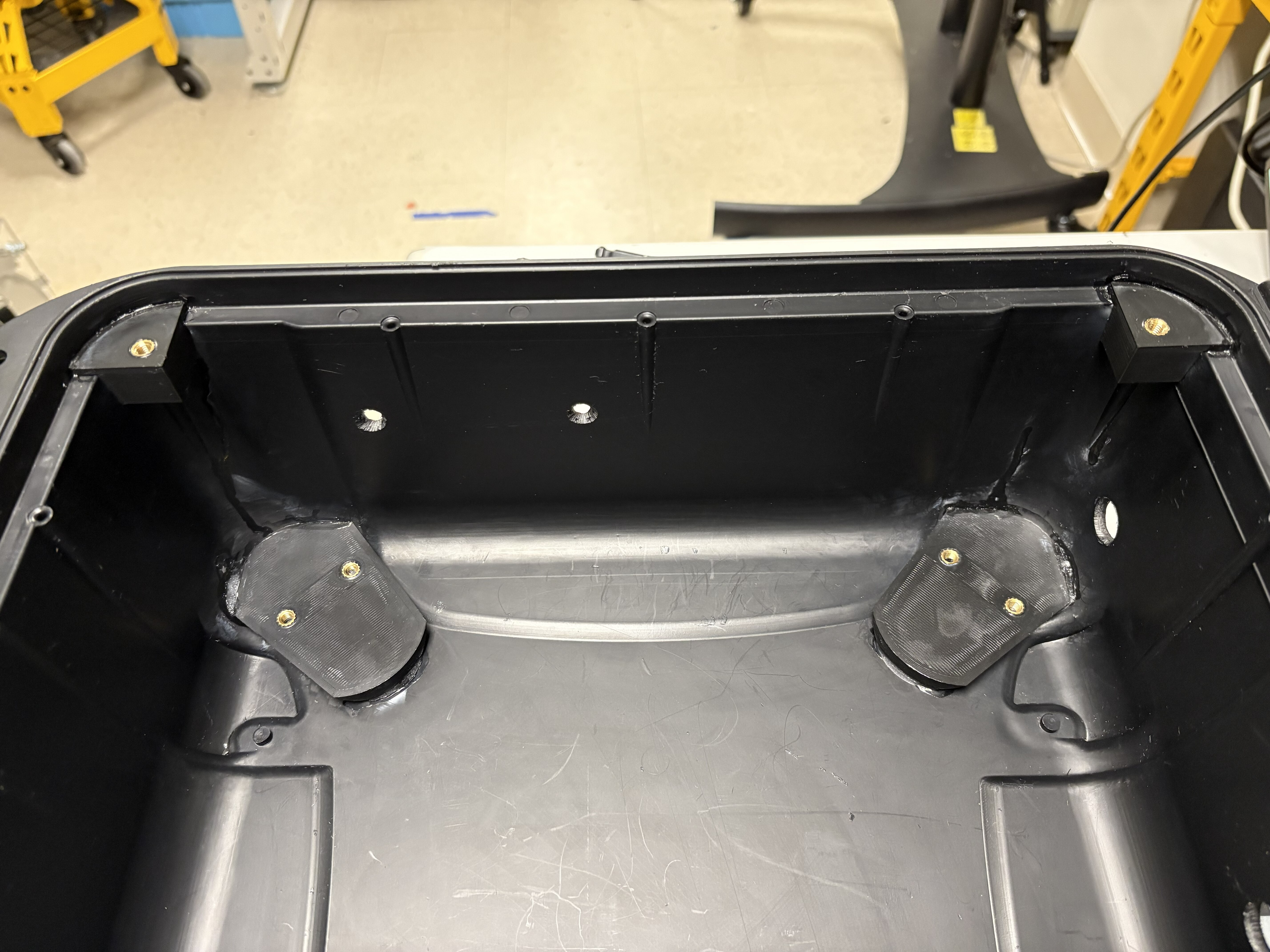
Figure 4. Top interface plate and mounting plate brackets.
External robot mounting system
Additional external mounting hardware was designed to allow the compute box to interface mechanically with the robot body. The mounting system is attached to the underside of the enclosure and allows the compute box to remain securely seated on the cylindrical body structure of the robot.
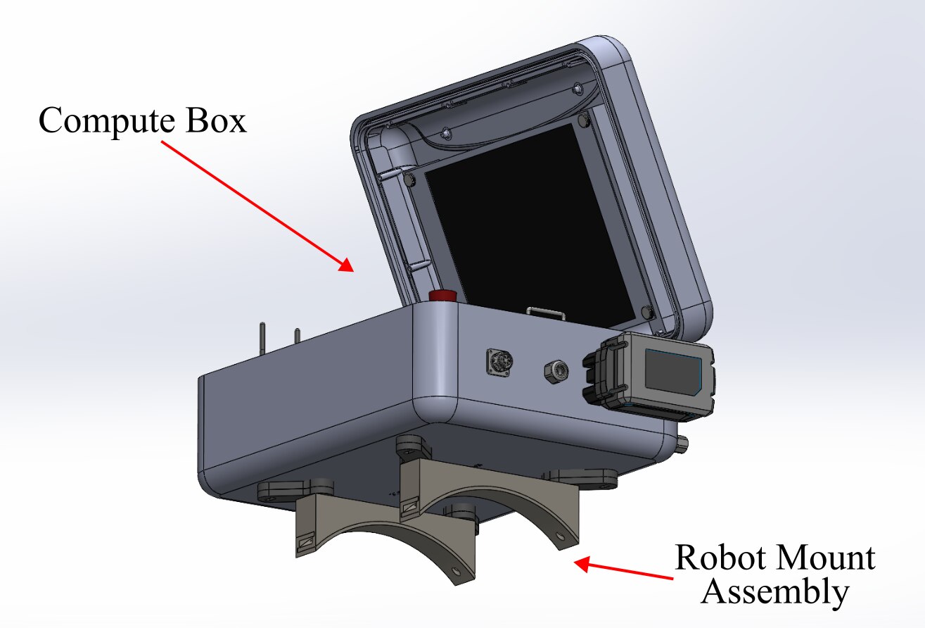
Figure 5. External robot mounting assembly attached to the underside of the enclosure.
Unlike the enclosure interior geometry, the exterior shell CAD for the NANUK 930 enclosure was not available from the manufacturer. As a result, the external mounting system was developed through manual measurements and iterative CAD refinement. The geometry was adjusted through repeated test fitting to achieve stable seating, proper enclosure fitment, and sufficient clearance for enclosure hardware and interfaces.
Mounting assembly
The robot mounting assembly consists of:
- a primary mounting bracket bonded directly to the enclosure
- an adjustment bracket with slotted mounting hole
- a curved support foot assembly
The primary mounting brackets are custom 3D printed and bonded to the enclosure underside using two-part epoxy. These brackets contain heat-set threaded inserts that provide the structural interface for the remaining mounting hardware.
The adjustment plates allow lateral positioning and alignment tuning relative to the robot body. The curved support feet were designed to match the cylindrical profile of the robot and improve seating stability during operation.
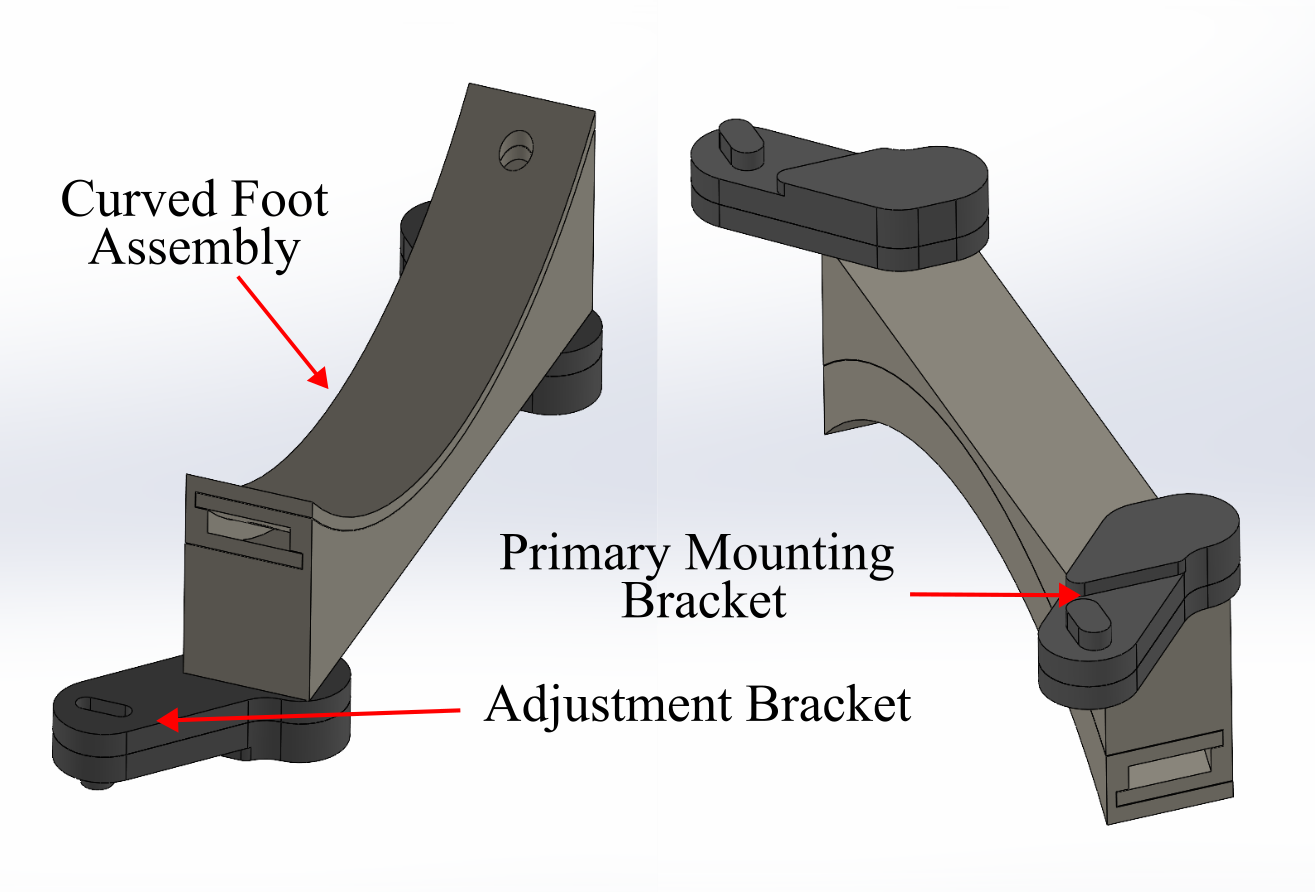
Figure 6. External robot mounting brackets and support feet assembly.
First, 3D-print the primary bracket mounts (4), install M5 heat-set inserts, and epoxy them to the bottom of the case.
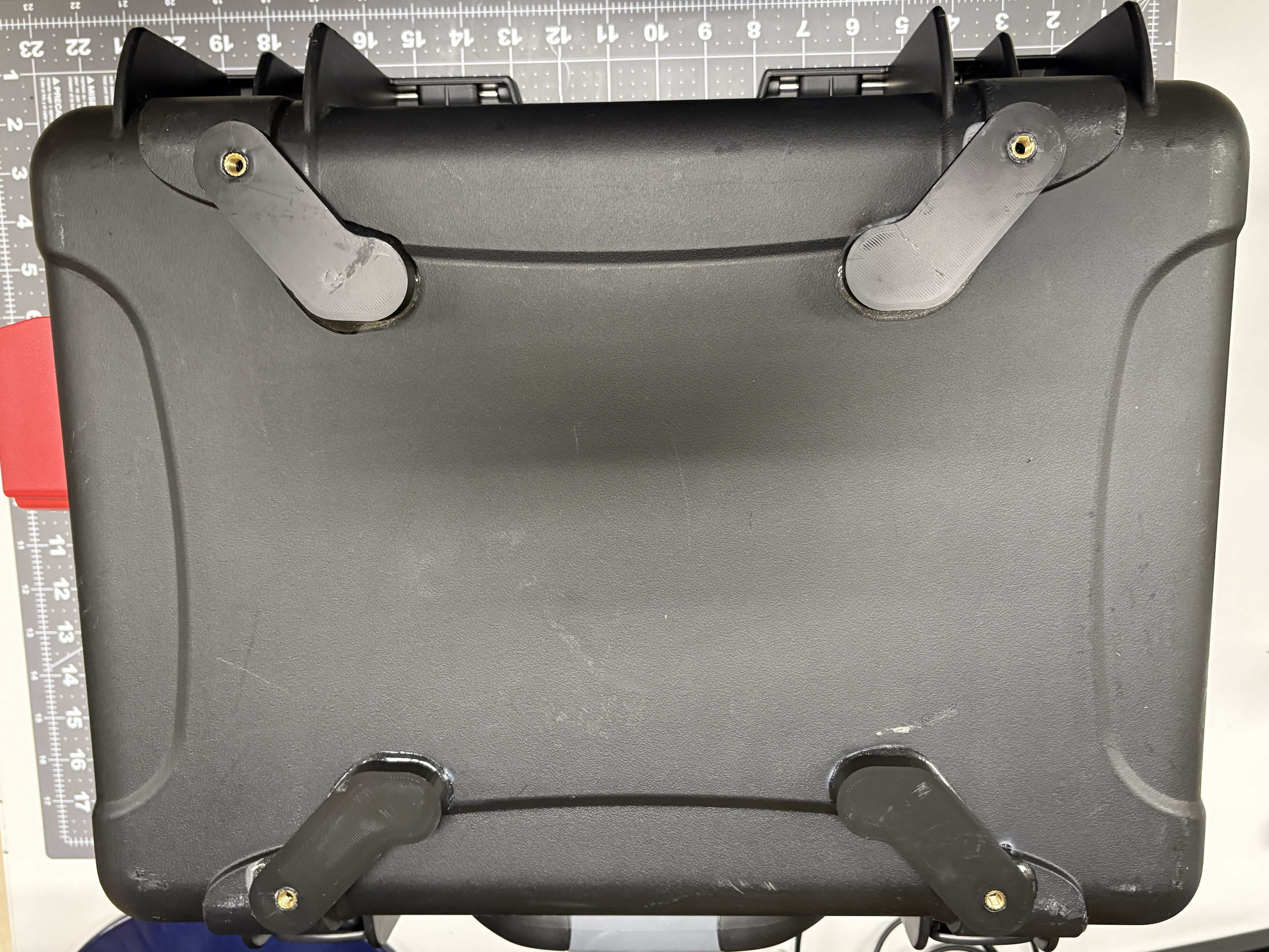
Figure 7. Primary brackets epoxied to the bottom of the case.
Then, 3D-print and assemble the curved foot assembly (2 sets). It is composed of two parts that slide and attach together. A few drops of super glue around the inner edges of the parts will make sure the parts are bonded strongly.
Next, 3D-print the adjustment brackets (4) and install M5 heat-set inserts. Then, use M5 fasteners to attach these to the foot assembly.
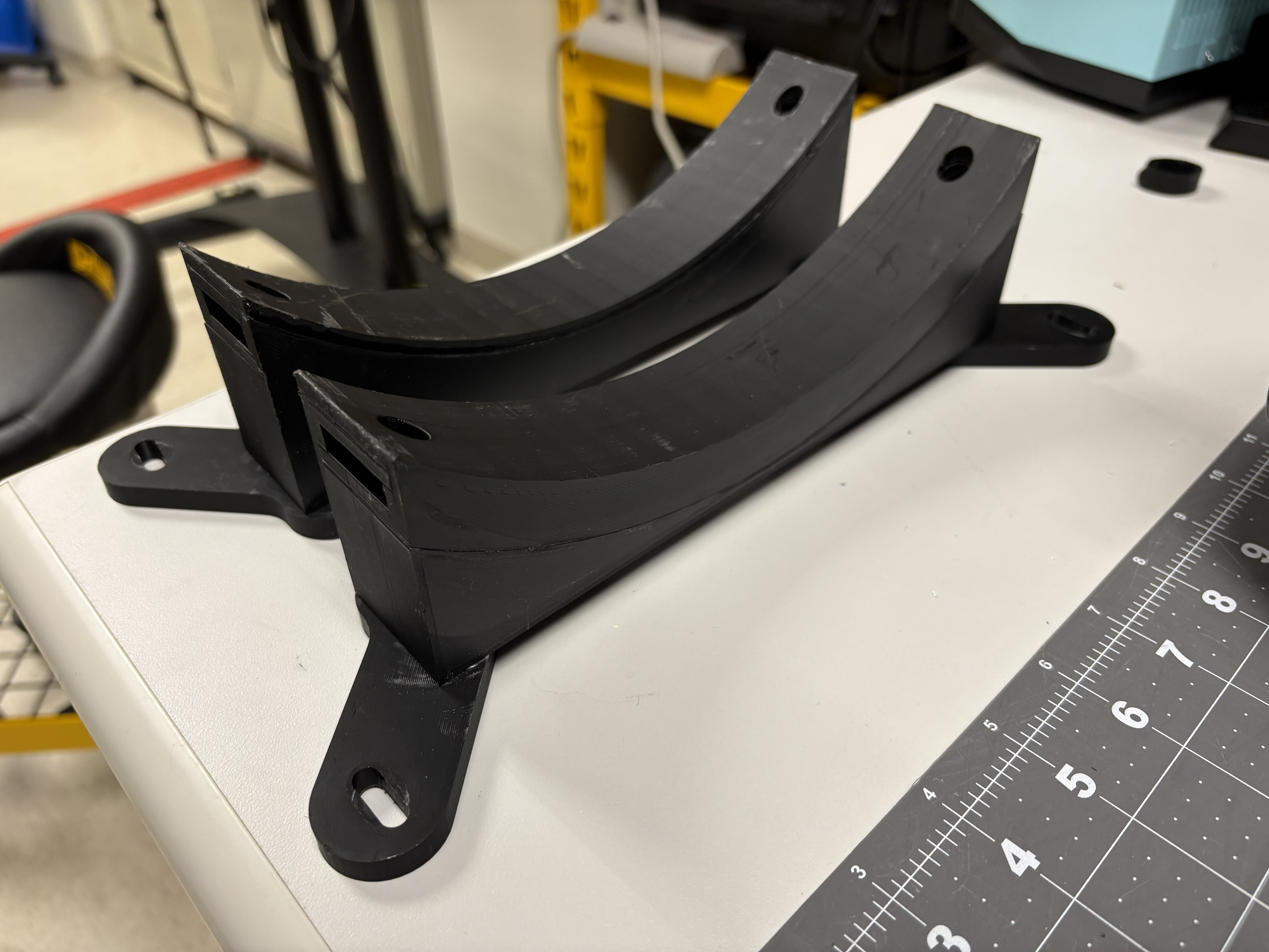
Figure 8. Curved foot assembly attached to the adjustment brackets.
Lastly, use M5 fasteners to attach the assembly to the primary mounting brackets.
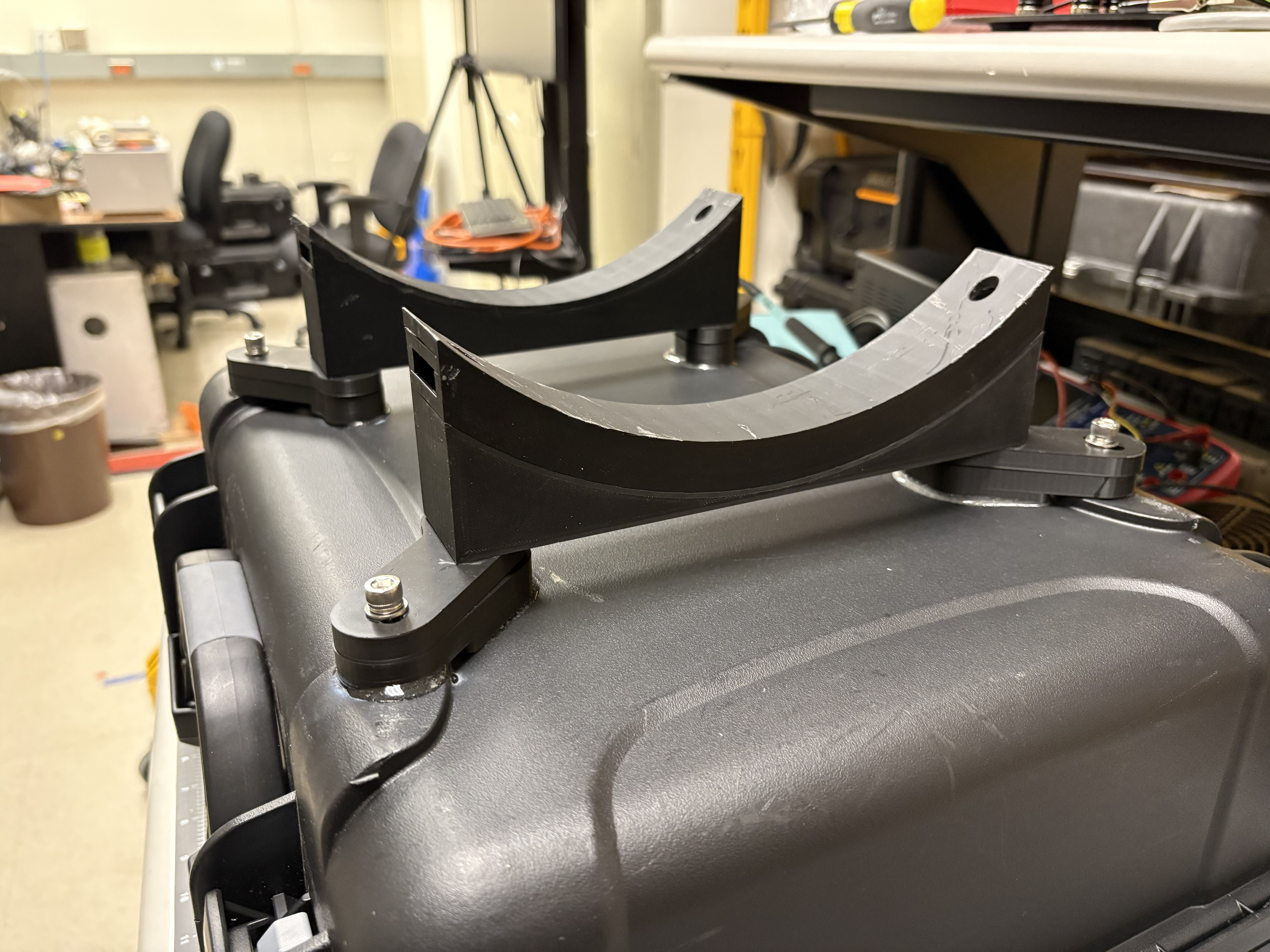
Figure 9. Installed external robot mounting assembly.
Screen mounting assembly
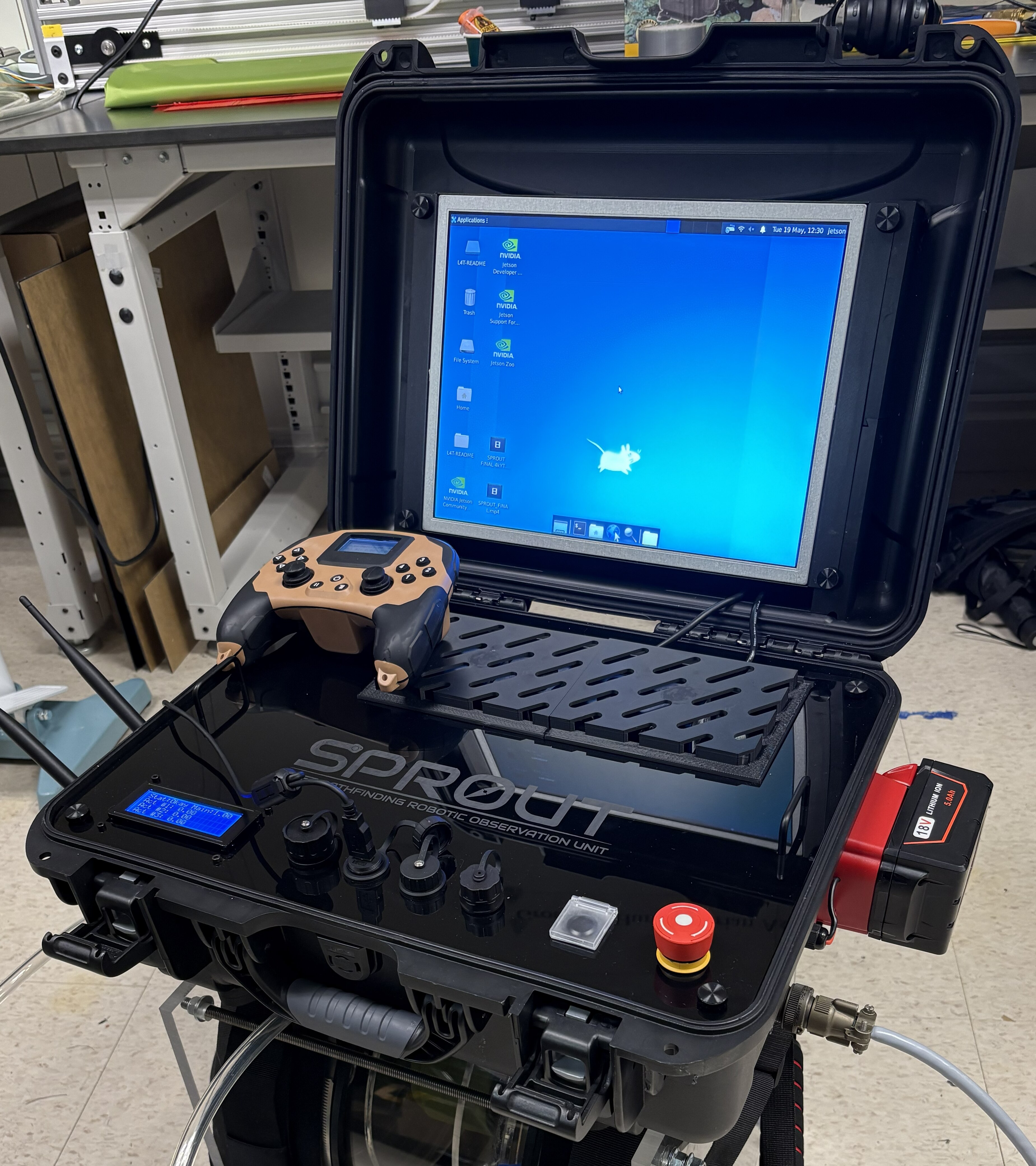
The last step in preparing the enclosure is to attach mounting structure for installing a screen. This screen is placed inside the lid of the case, so that when the case is opened, the user can see the peripherals panel in the bottom and the screen in the lid, like a laptop.
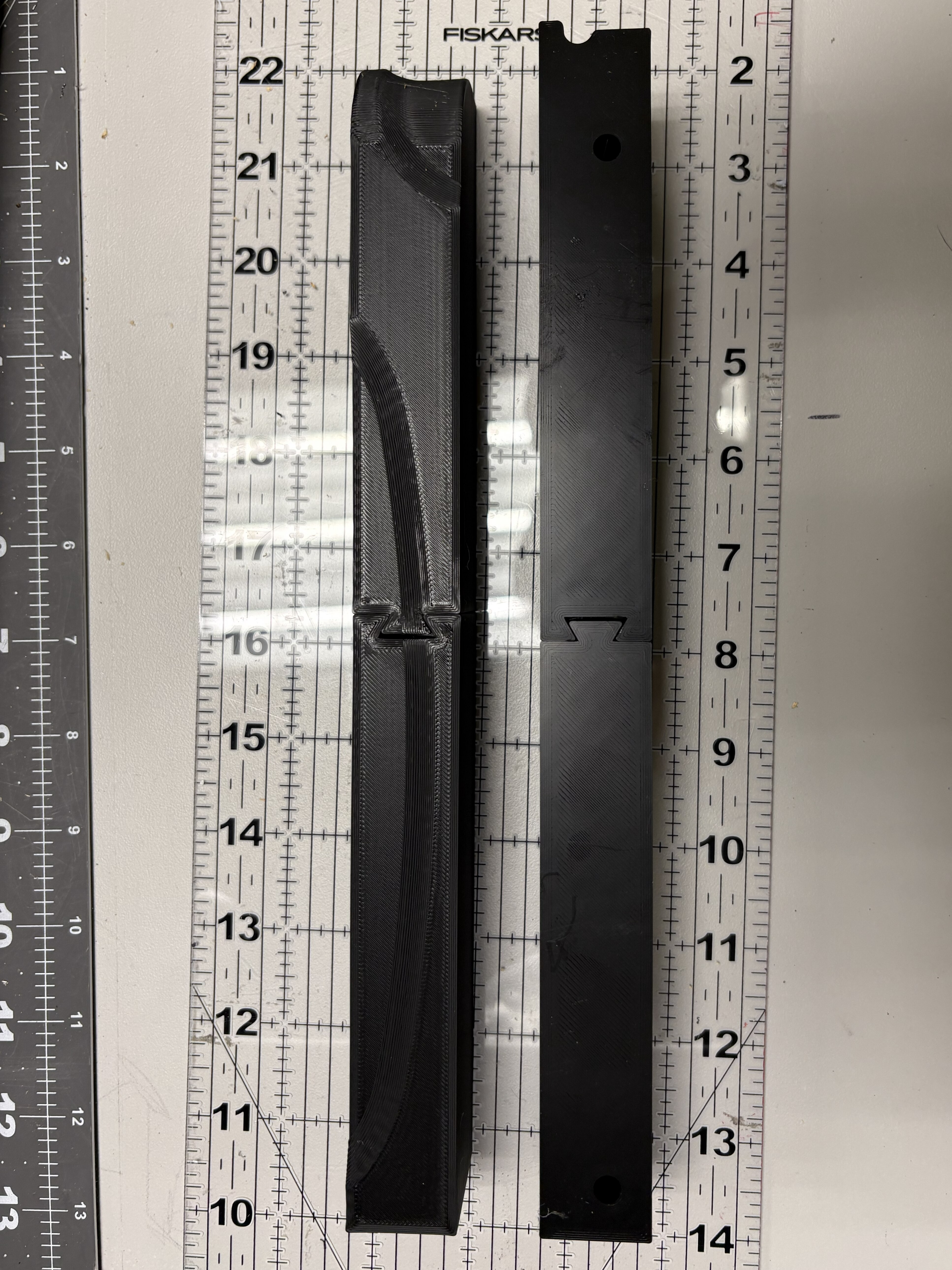
First, 3D print the screen mounting brackets, provided in the CAD section. These were designed using the inner shell of the case so that they perfectly rest on the features of the inner wall of the lid. Depending on your 3D-printer bed size, you may need to cut these into two sections so they fit on the build plate, as shown below.
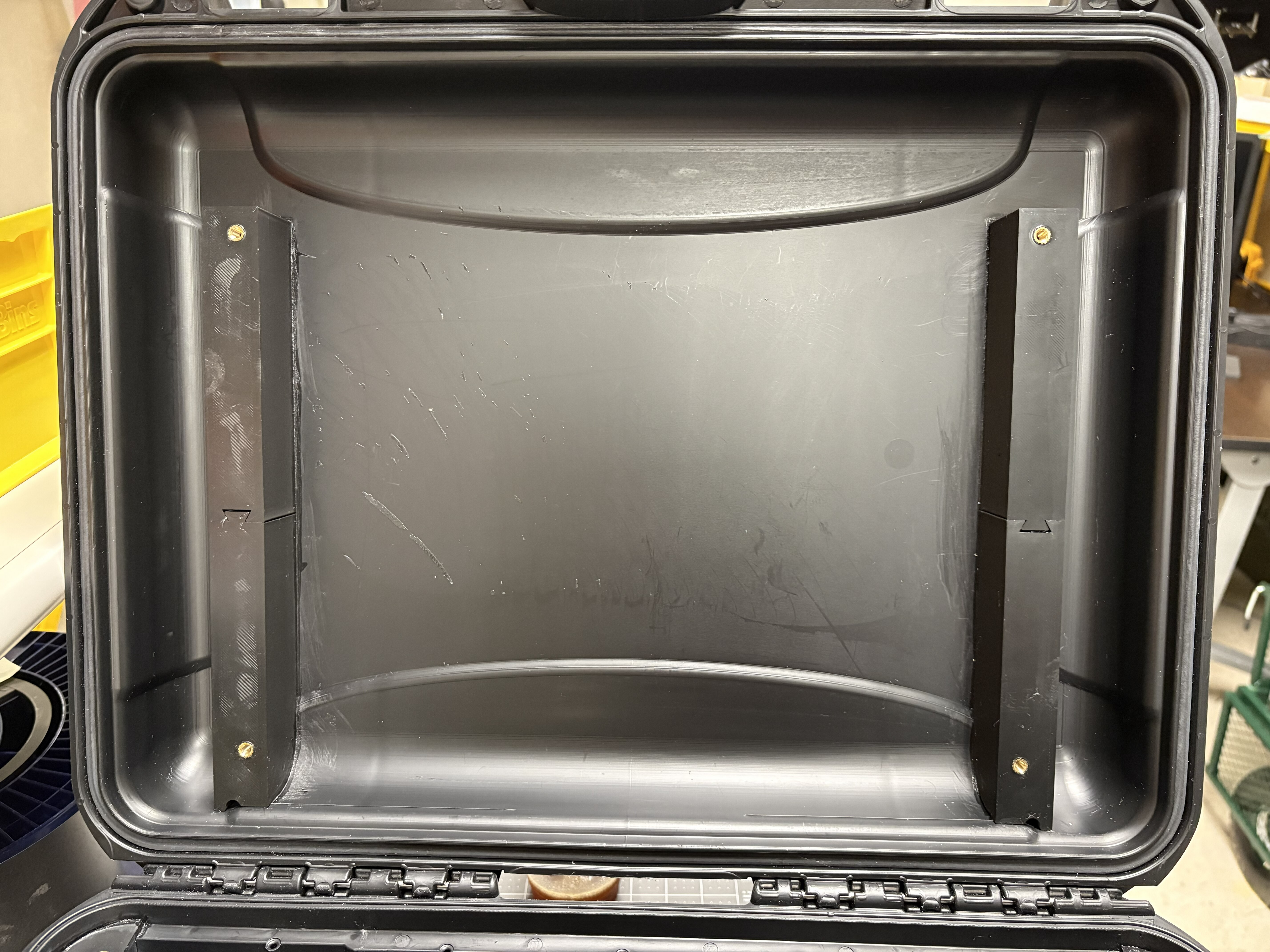
Install M5 heat-set inserts in the holes (two on each bracket). Adhere the brackets to the case using epoxy, lining the printed parts with the wall features, and resting in the bottom of the lid. The end product should look as below.
Next: continue with the Compute Box.