Compute Box Assembly
This page provides step-by-step instructions for assembling the SPROUT compute box following enclosure preparation.
Before beginning assembly, ensure that:
- enclosure preparation is complete
- all bonded components have fully cured
- all hardware listed in the BOM is available
Table of contents
- Assembly overview
- Step 1: Mount electropneumatic hardware
- Step 2: Install power subsystem
- Step 3: Install compute hardware
- Step 4: Electrical connections
- Step 5: Install external elements
- Step 6: Install communication interfaces
- Step 7: Screen installation
- Step 8: Assembly with robot base
- Step 9: Final inspection
- Next steps
Assembly overview
Assembly proceeds in the following order:
- Install electropneumatic hardware
- Install power subsystem
- Mount compute hardware
- Set electrical connections
- Install external elements
- Mount communication interfaces
- Screen installation
- Assembly with robot base
- Final inspection
Step 1: Mount electropneumatic hardware
Required components
| Item | Qty |
|---|---|
| QB3 Pressure Regulators | 4 |
| Solenoid Valve 3/2 NC | 1 |
| 1/4” Push-to-Connect OD x 1/4” NPT Thread Tee | 3 |
| 1/8” Push-to-Connect OD x 1/16” NPT Thread Tee | 3 |
| 1/4” Push-to-Connect OD x 1/4” NPT Thread Elbow | 2 |
| 1/8” Push-to-Connect OD x 1/16” NPT Thread Elbow | 1 |
| 1/4” Push-to-Connect OD x 1/4” NPT Thread Straight Connector | 1 |
Procedure
-
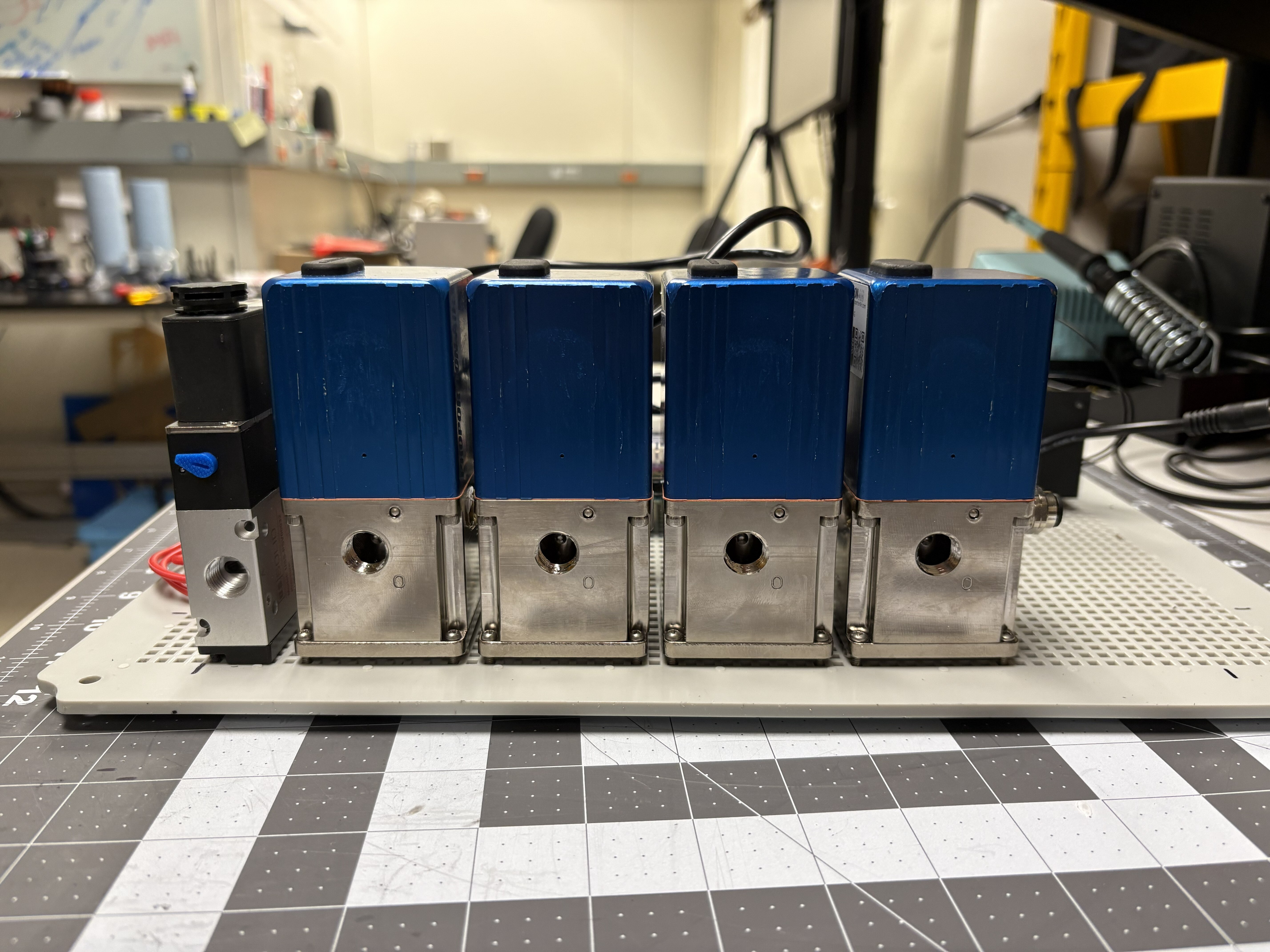
Position the QB3s and solenoid valve in the mounting plate. Secure to plate with adequate hardware. Make sure to line up the elements so the output ports are facing towards the outside of the plate, as shown below.
-
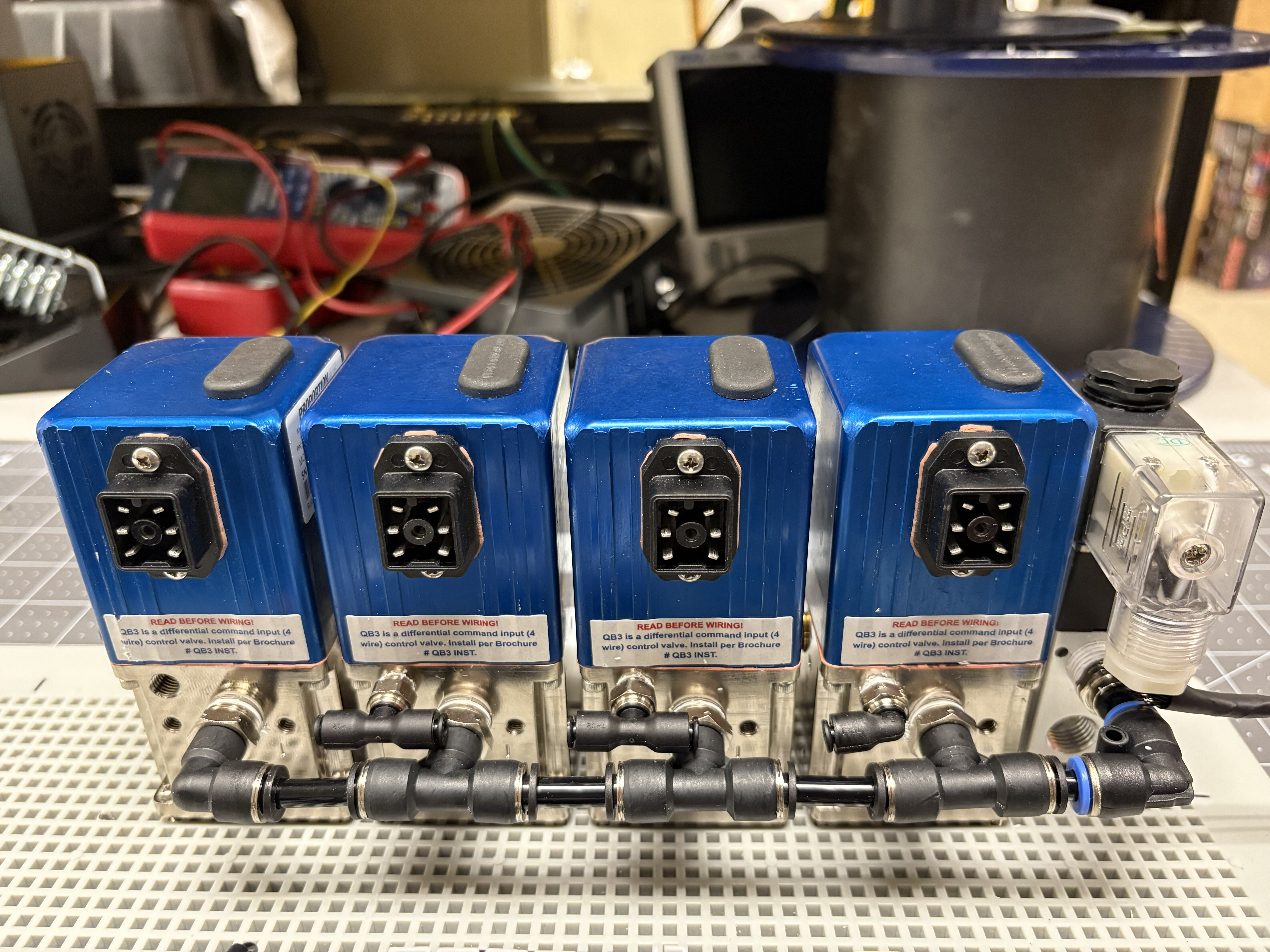
Install the 1/4” Push-to-Connect OD x 1/4” NPT Thread Tee (3) and Elbows (2) in the electropneumatic components as shown. Plug in tubing to interconnect the elements pneumatic lines. These are the inlet ports of the pressure regulators.
-
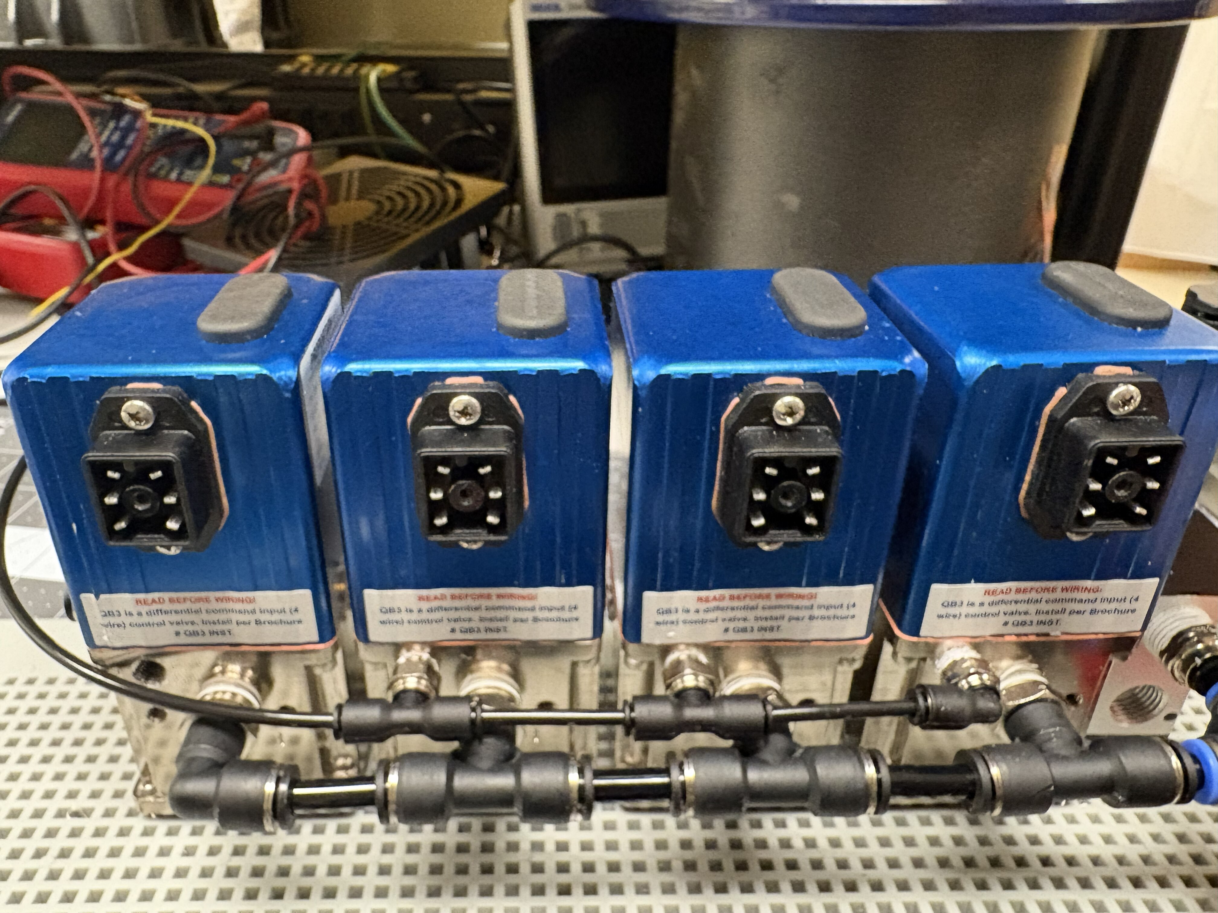
Install the 1/16” Push-to-Connect OD x 1/8” NPT Thread Tee (3) and Elbows (2) in the electropneumatic components as shown. Plug in tubing to interconnect the elements pneumatic lines. These are the front exhaust ports of the pressure regulators.
-
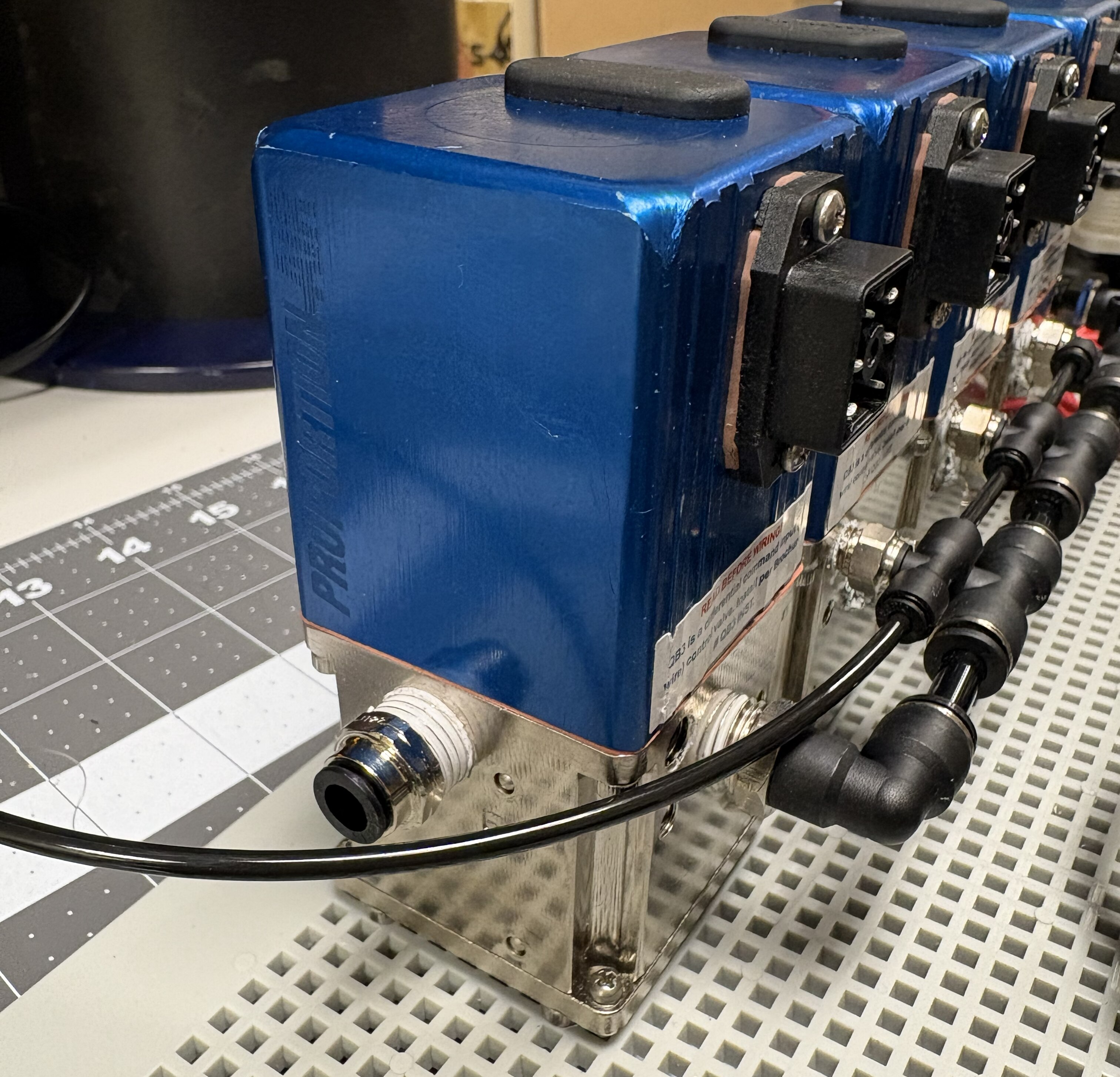
Install a 1/4” Push-to-Connect OD x 1/4” NPT Thread Straight Connector in the last QB3 side exhaust port.
-
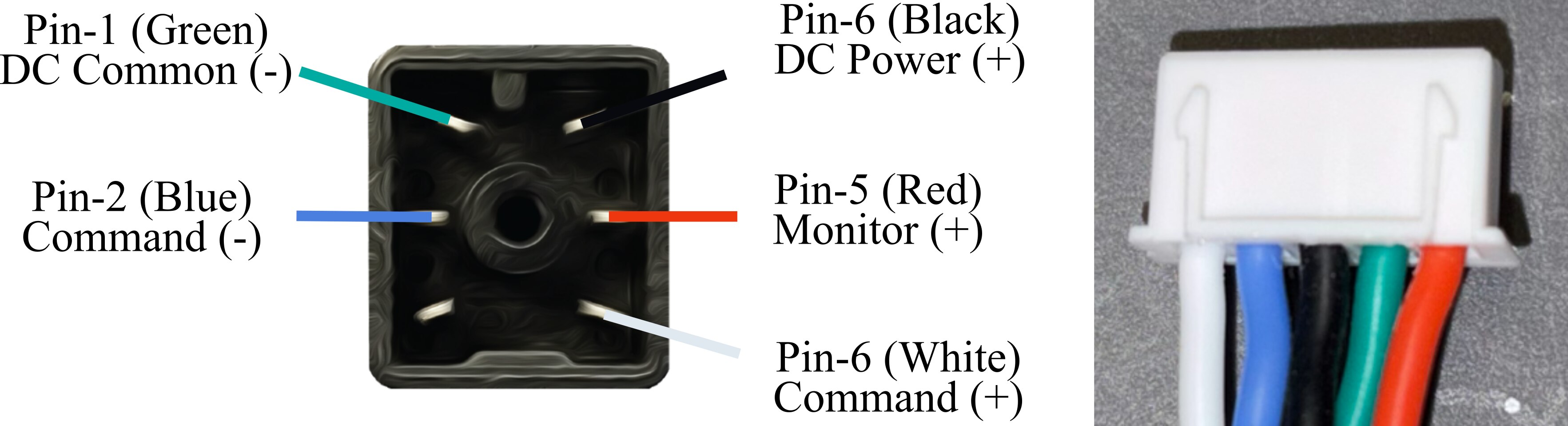
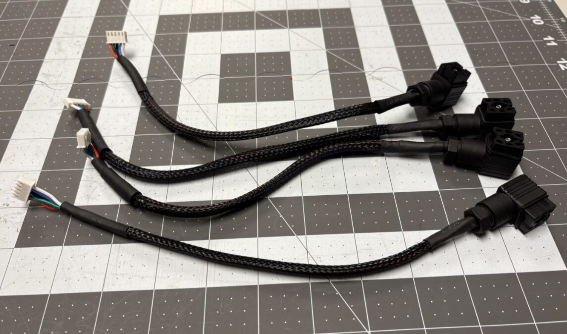
Solder one end of 5 - 22 AWG stranded wires (~12 inches long each) to the QB3 connector’s terminals. Cover wires with braided wire sleeving and insert two heat shrink tubing section of about an inch each. On the other end of the wire, crimp the ends and install on a 5-pin JST-HX connector. Follow the wiring diagram to have wires in the right order on the connector. Use a hot air gun to shrink the tubing. Repeat this process to make 4 connectors, like shown below.
-
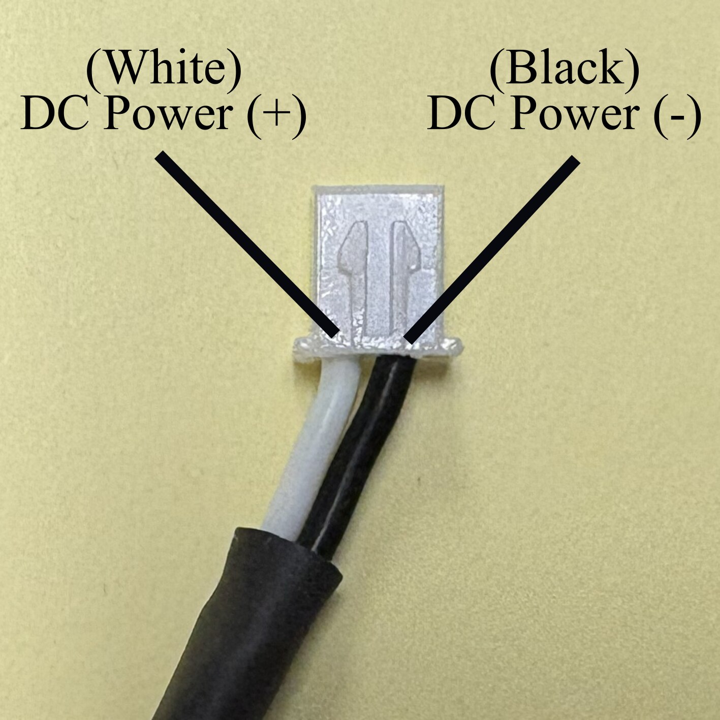
Solder one end of 2 - 22 AWG stranded wires (~12 inches long each) to the solenoid terminals (white to DC power +, black to DC power -). Cover wires with braided wire sleeving and insert two heat shrink tubing section of about an inch each. On the other end of the wire, crimp the ends and install on a 2-pin JST-HX connector. Follow the wiring diagram to have wires in the right order on the connector. Use a hot air gun to shrink the tubing.
Step 2: Install power subsystem
Required components
| Item | Qty |
|---|---|
| Battery Adapter | 1 |
| Cord gland | 1 |
| Buck Converters | 4 |
| Fuse Holders | 5 |
Procedure
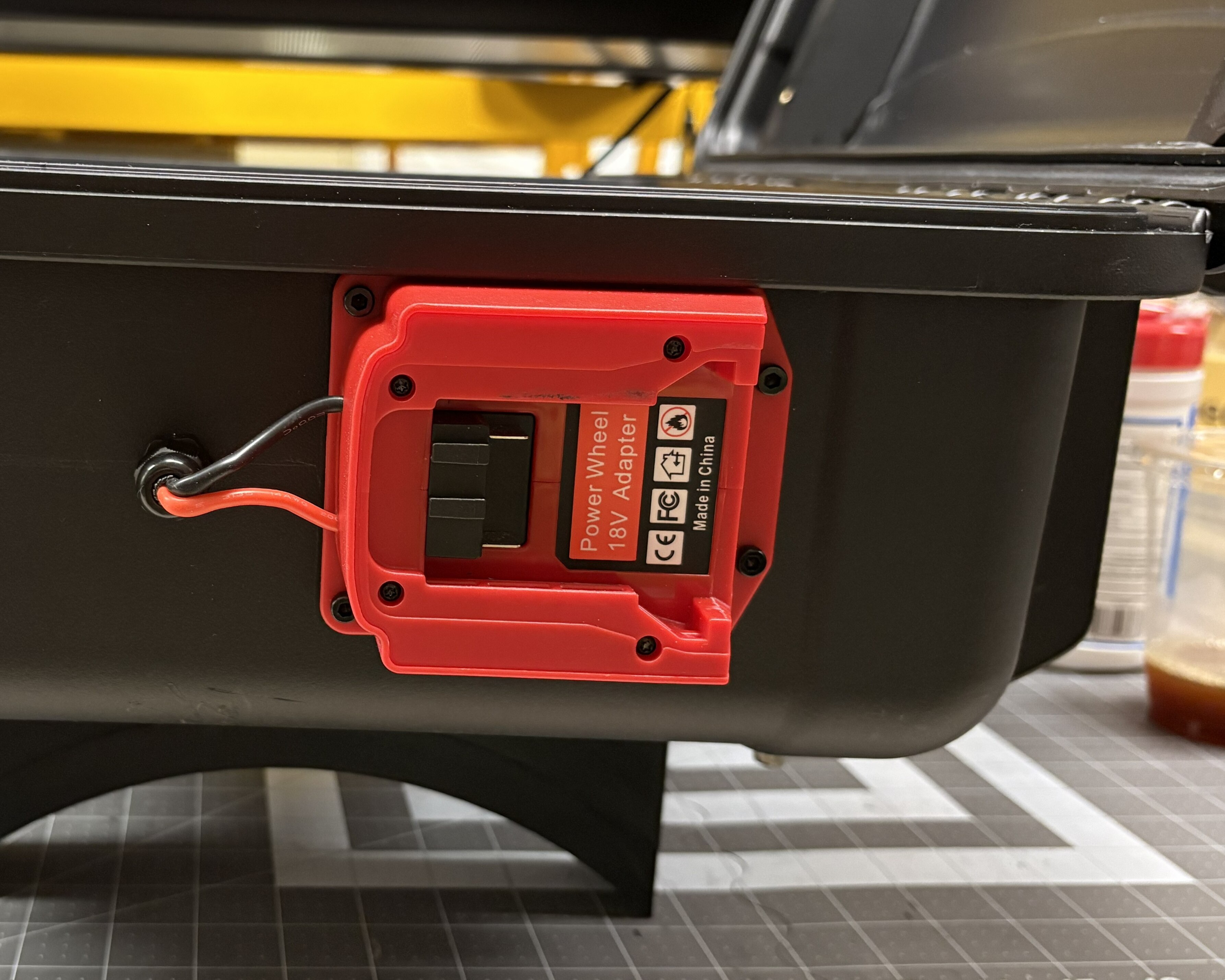
- Mount the battery adapter to the external right side of the case. To do so, place the adapter flush against the top border (as shown below) and mark down the screw holes. Drill these out and install using appropriate fasteners.
- The battery adapter usually comes with a fuse holder in line. Cut the wires to get rid of the fuse holder.
-
Drill a 1/2” hole next to the battery adapter, and install the cord gland. Pass the wires through it to the inside of the case, and tighten the gland.
-
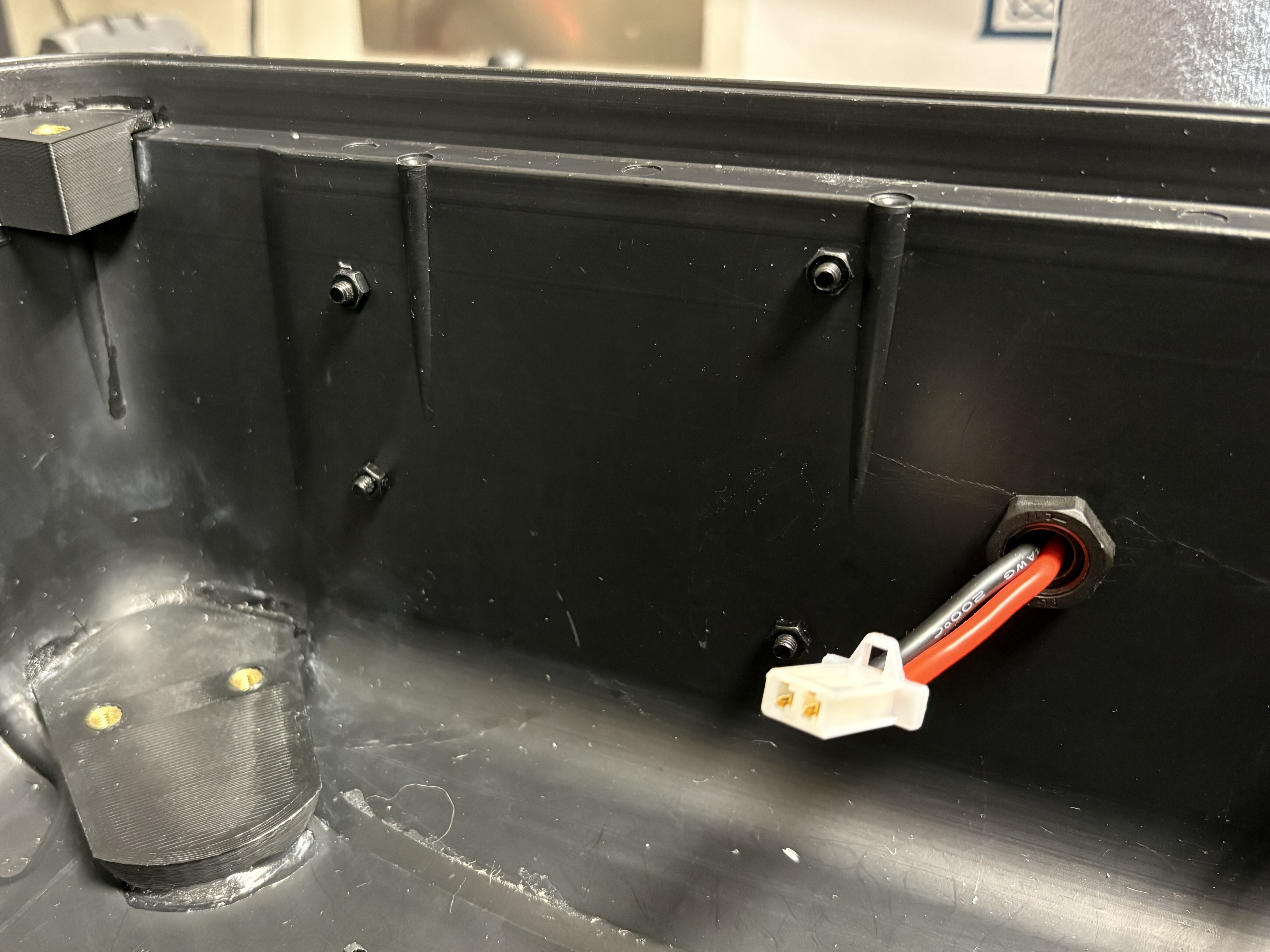
Once inside, crimp the wires and install a 2.8mm 2-pin male connector. See below.
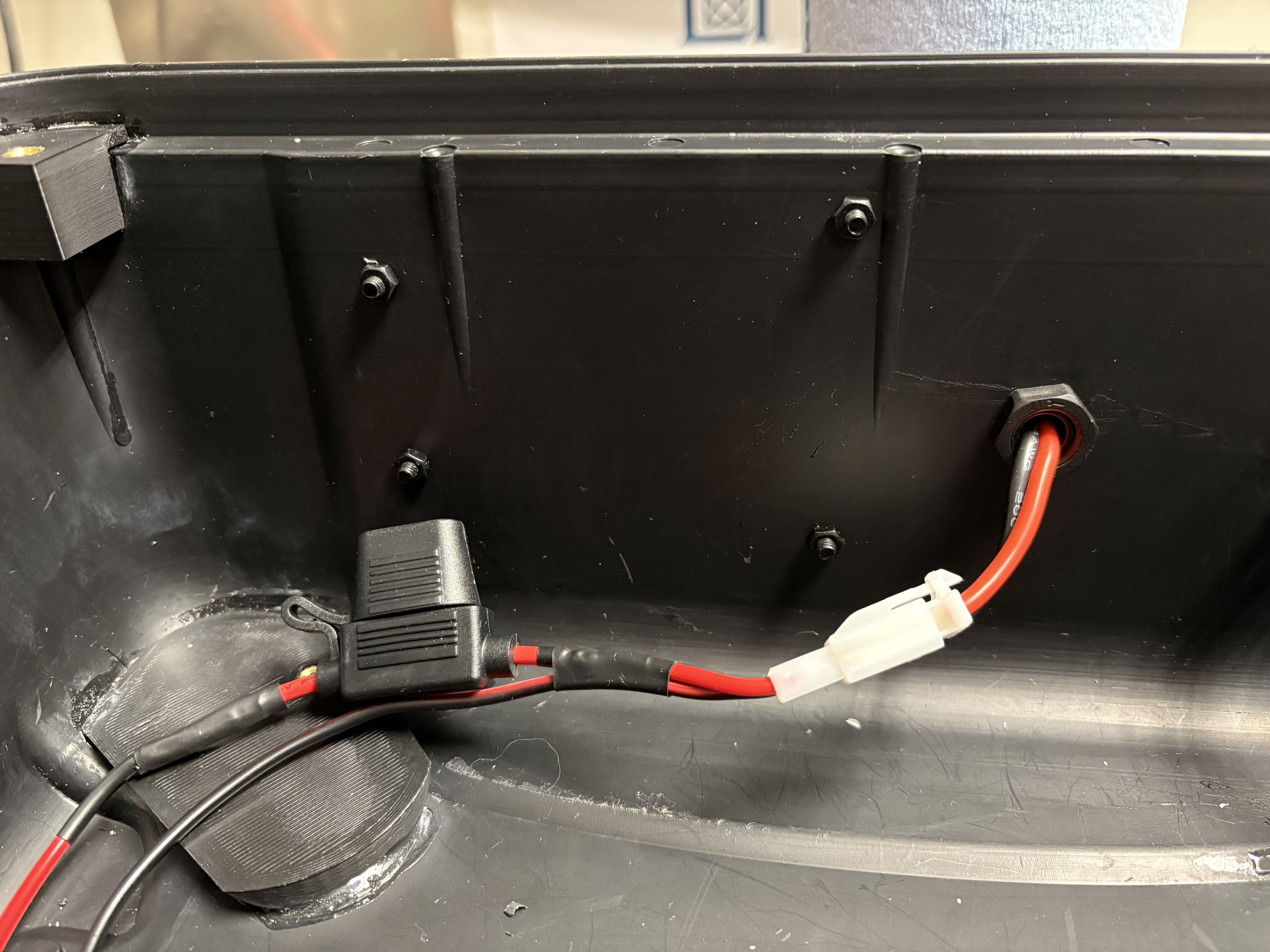
- Crimp one end of an in-line fuse holder and a 16 AWG black wire (about 12” long) and install a 2.8mm 2-pin female connector. On the free end of the fuse holder, solder a 30” long 16 AWG red wire, and cover the solder with heat-shrink tubing.
-
Connect the 2.8mm connectors. Install a 20A fuse in the holder.
-
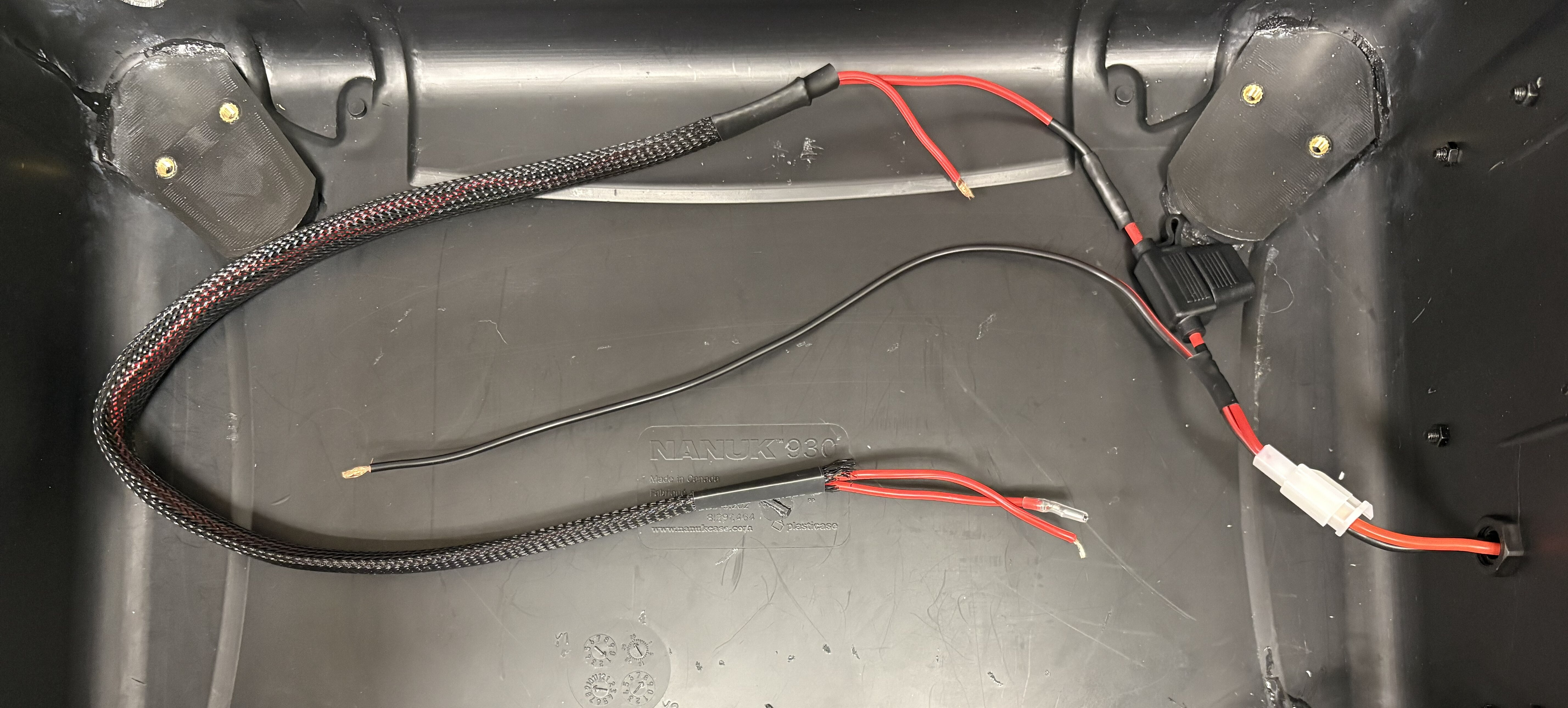
Cut about 30” of red 16 AWG wire. Along with the other 30” long red wire, cover them with braided wire sleeving and insert two heat shrink tubing section of about an inch each. Leave both ends of the new wire free for now.
- Solder about 15” of 16 AWG wire to the INPUT end of each of 4 buck converters (red for POWER, black for GND). Solder another 15” of 16 AWG wire to the OUTPUT pins (red for POWER, black for GND).
- Cut the output POWER wire (red) of each buck converter about 5” from the boards, and install an in-line fuse holder by soldering and applying heat-shrink tubing.
- For one of the buck converters, cut both the PWR and GND wires a few inches after the in-line fuse holder, and solder them to the end wires of a 3-ft long DC barrel plug cable. Install a 3A fuse in the fuse holder. This will be the power cord for the screen.
- For another buck converter, cut about 3” of the leftover PWR and GND wires, and solder them to the end wires of a 6” long DC barrel plug cable. Install a 3A fuse in the fuse holder. This will be the power cord for the Jetson Nano.
-
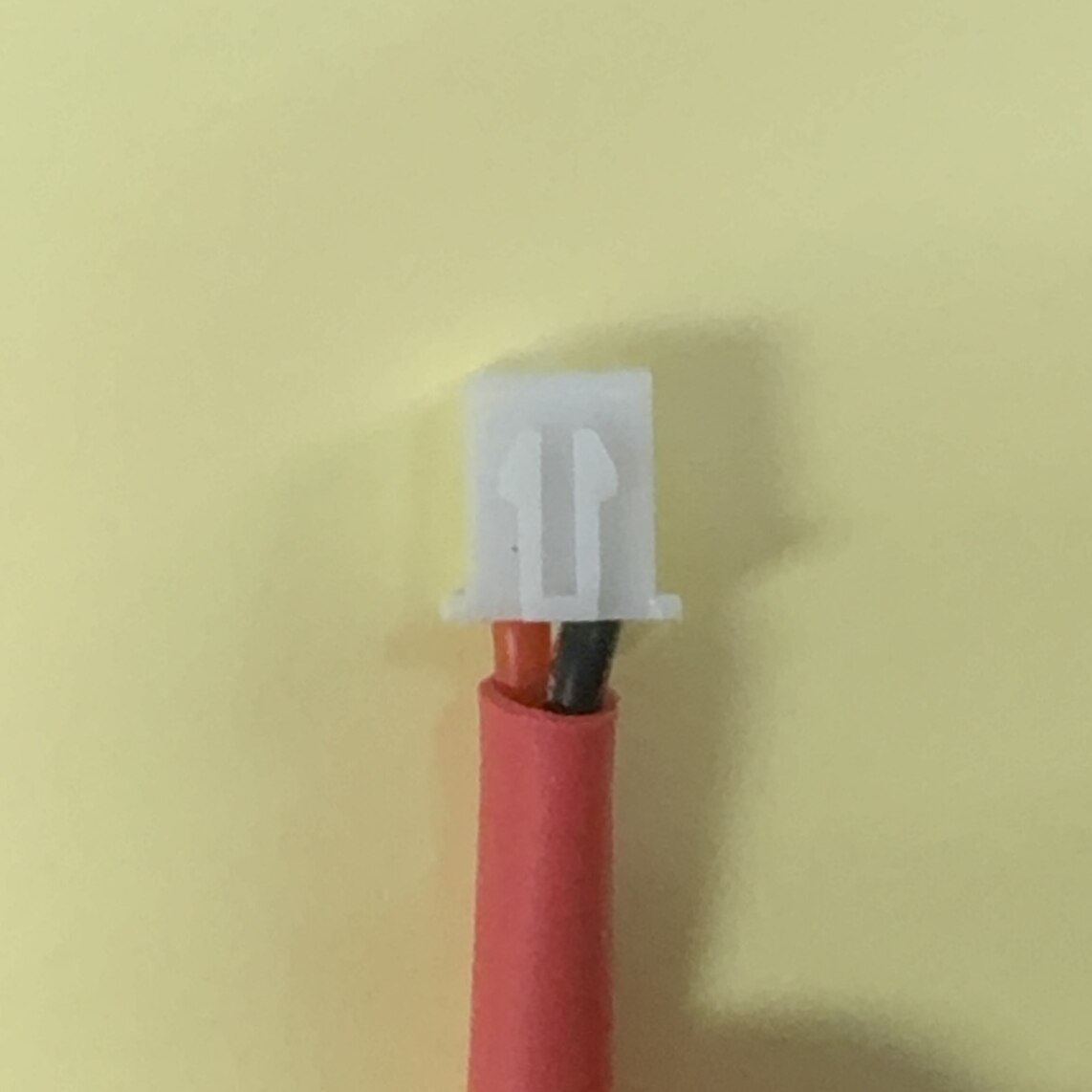
For two of the leftover converters, install 2-pin JST-HX male connectors in the free ends. Refer to the image for the wire order in the connector. Install 5A fuses in the fuse holders of these power lines.
- Stack the buck converters using M3 standoff spacers, with the barrel plug one all the way to the top.
-
Connect all 4 input POWER wires from the buck converters to a 5-pin lever wire connector. Do the same for all 4 input GND wires. The end product should look as below.
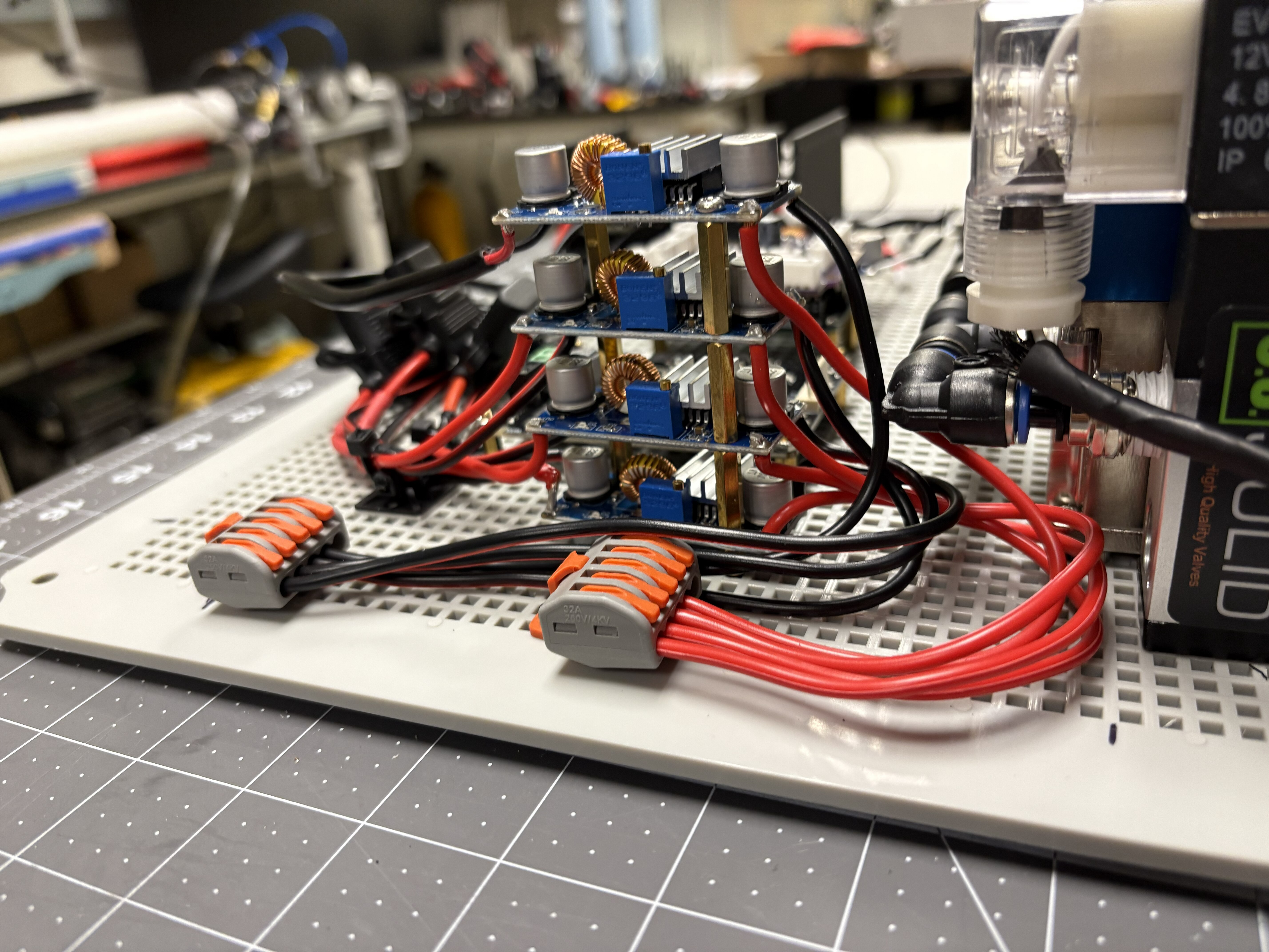
-
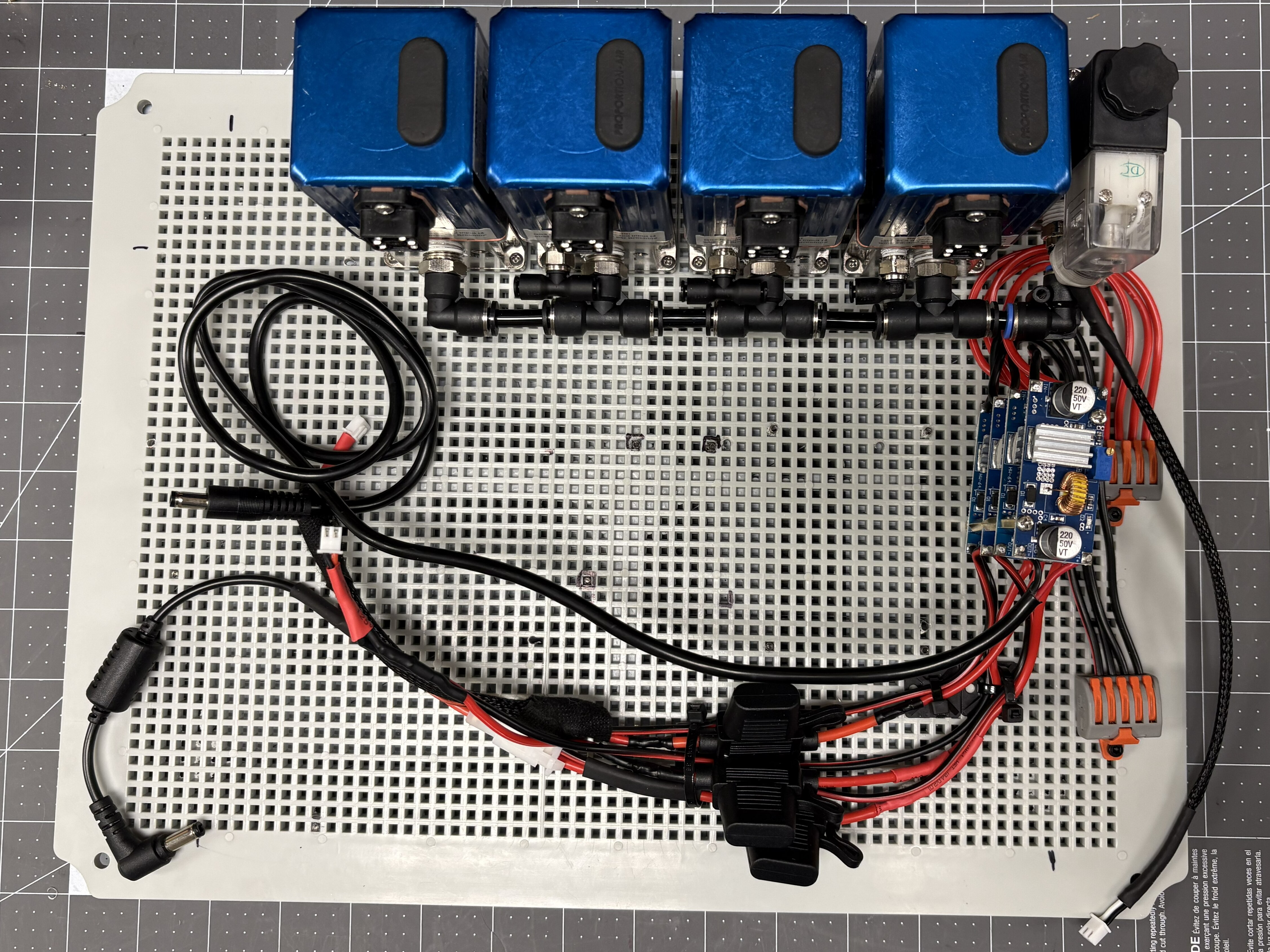
Secure the stacked buck converters and lever connectors to the plate using fasteners. Use zip ties and adhesive tie mounts to hold wiring in place on the plate.
-
Up to this point, the mount plate should look similar to the image shown below. (This picture does not show the 1/8” tubing connections between exhaust ports — make sure you have those in place; see Step 1.3.)
- Connect an 18V power supply to the lever connector and adjust all the buck converters output voltage to 15V. Disconnect power supply when done.
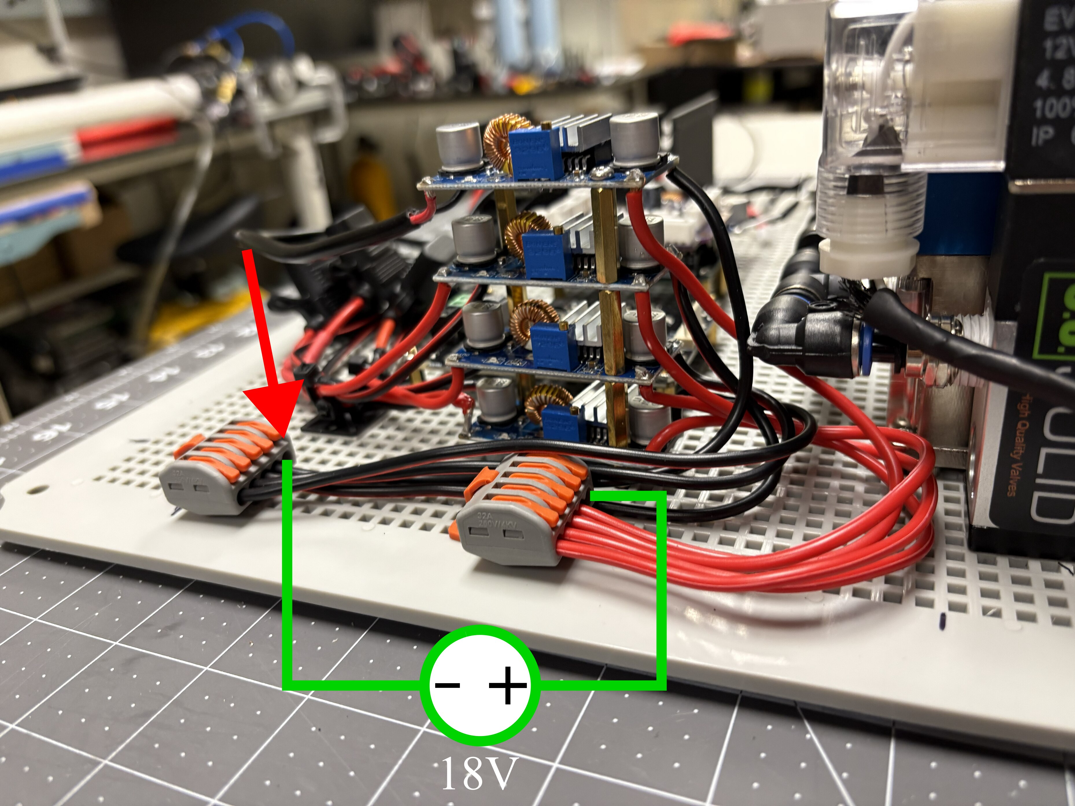
Double-check every buck converter output reads 15V before it is wired downstream. Compute and peripheral hardware connected to an over-voltage rail can be permanently damaged.
Step 3: Install compute hardware
Required components
| Item | Qty |
|---|---|
| NVIDIA Jetson Nano | 1 |
| Jetson 3D-printed housing | 1 |
| Arduino Uno Rev3 | 1 |
| Custom Arduino Shield PCB | 1 |
| DC Motor Driver | 1 |
| Buck Converters | 1 |
| Dual-Mode Wireless NIC Module | 1 |
Procedure
-
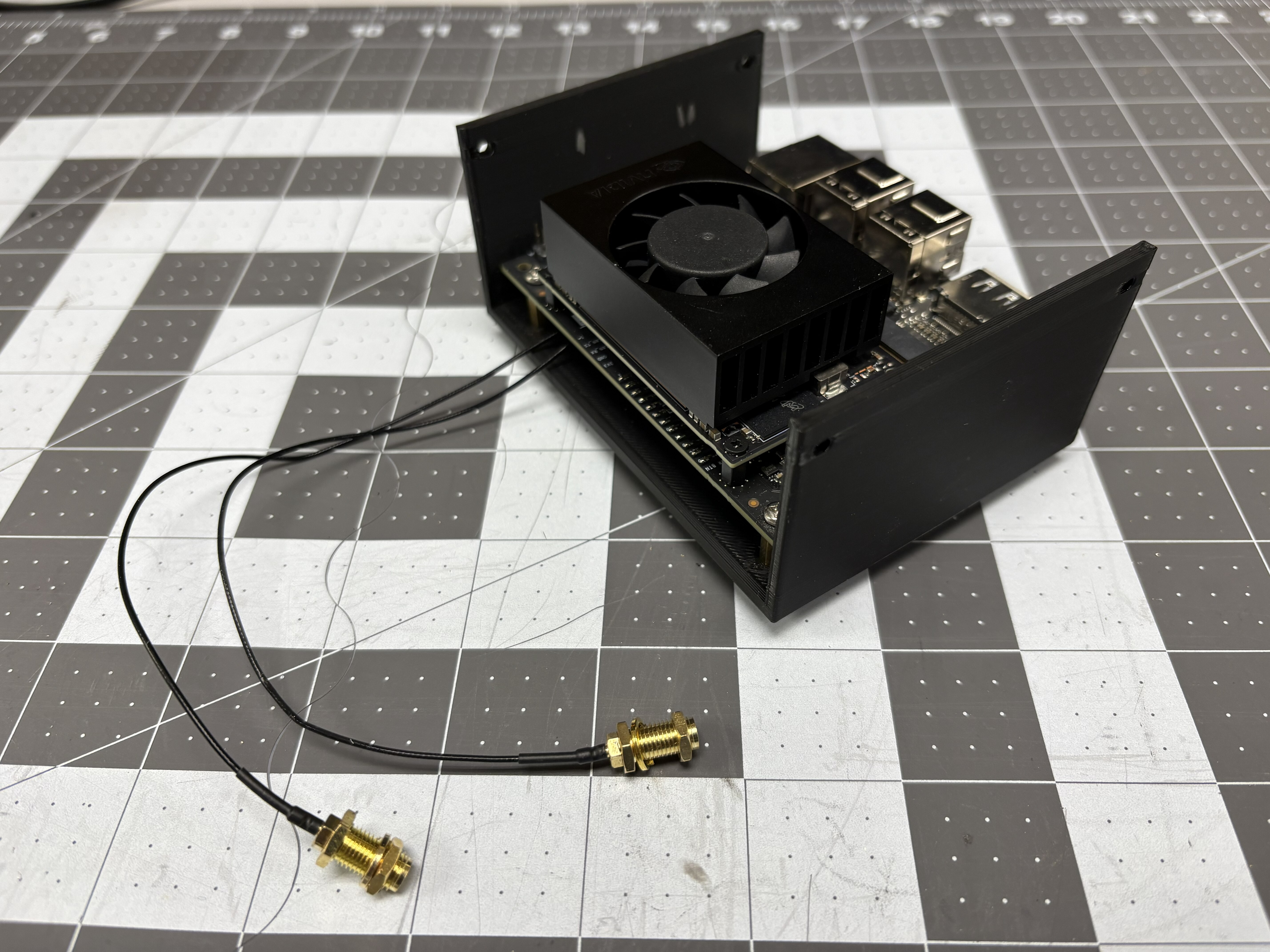
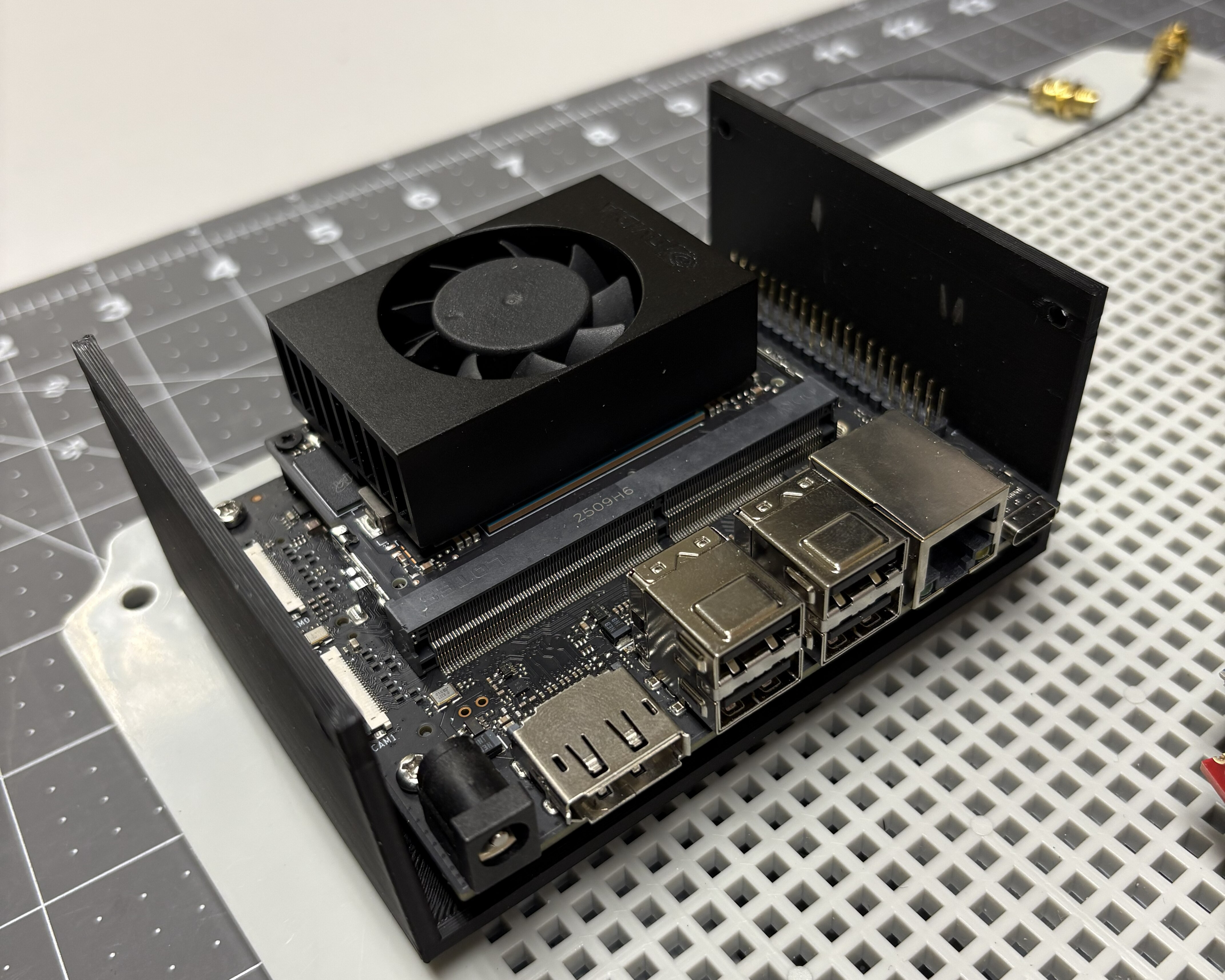
Install wireless NIC module to Jetson. Connect the antenna cables. Mount the Jetson computer to the 3D-printed housing using appropriate fasteners. Mount assembly to plate.
-
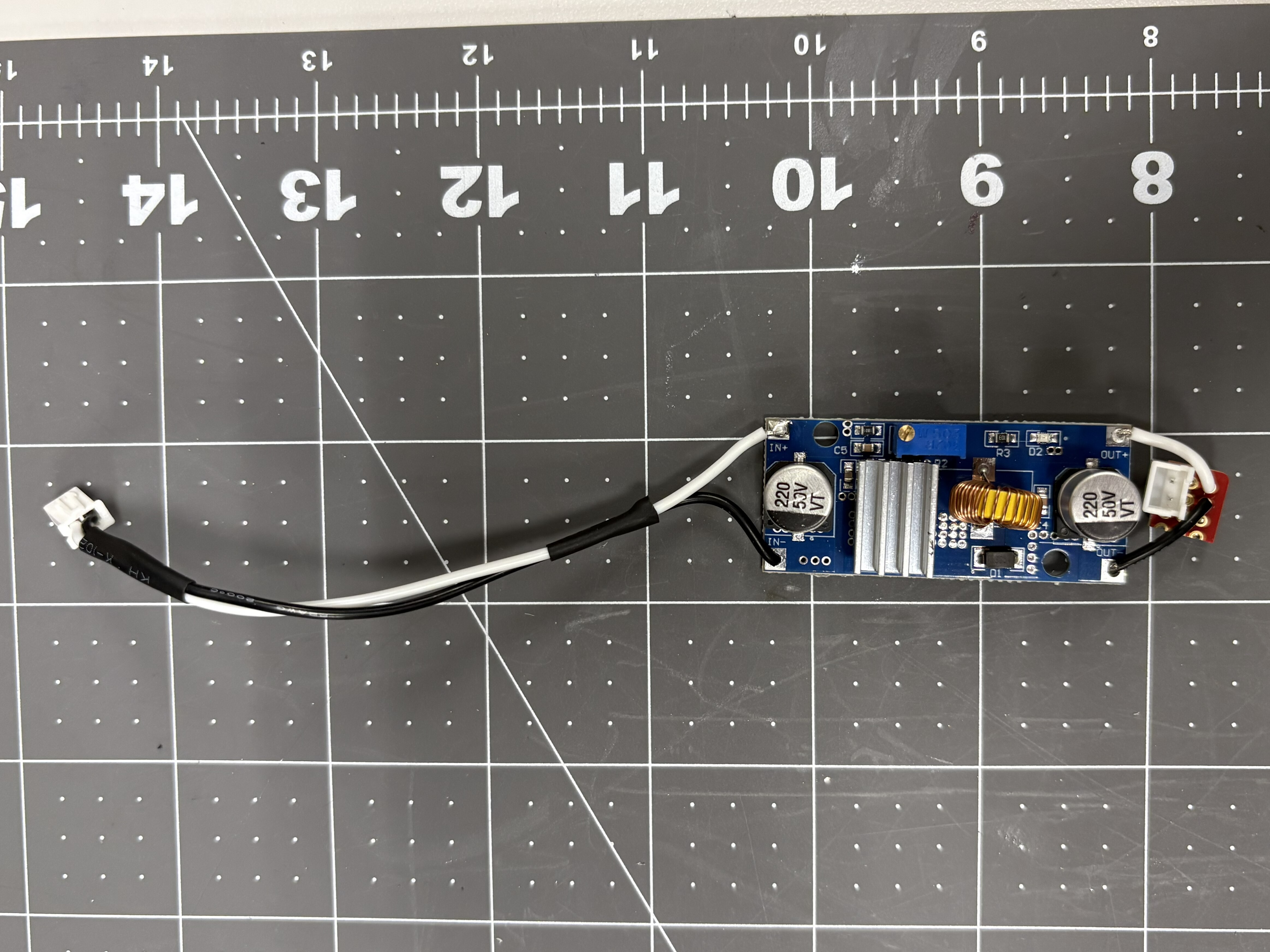
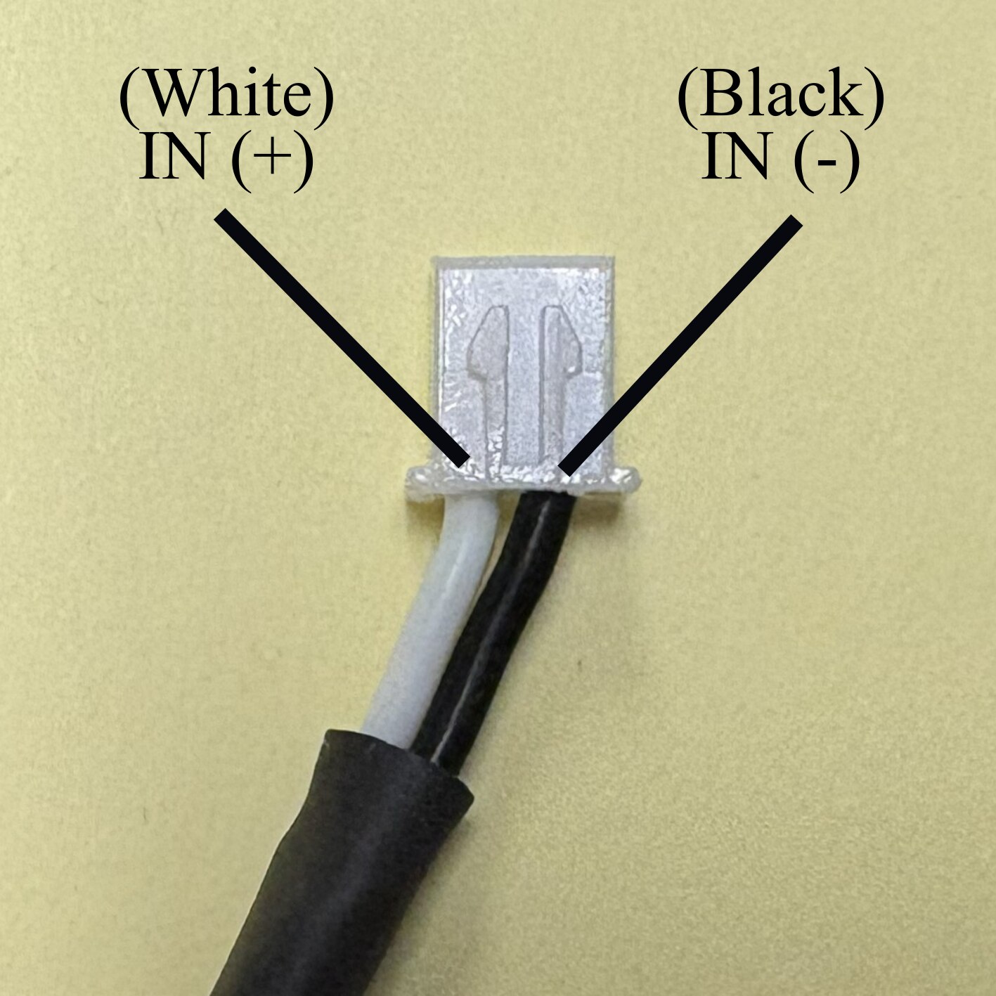
Solder about 5” of 22 AWG stranded wire to the INPUT of a buck converter and install a JST-HX male connector. Solder about 2” of 22 AWG stranded wire to the OUTPUT of this buck converter, and install a JST-HX female connector. Follow the image below to have wires in the right order on the connectors.
-
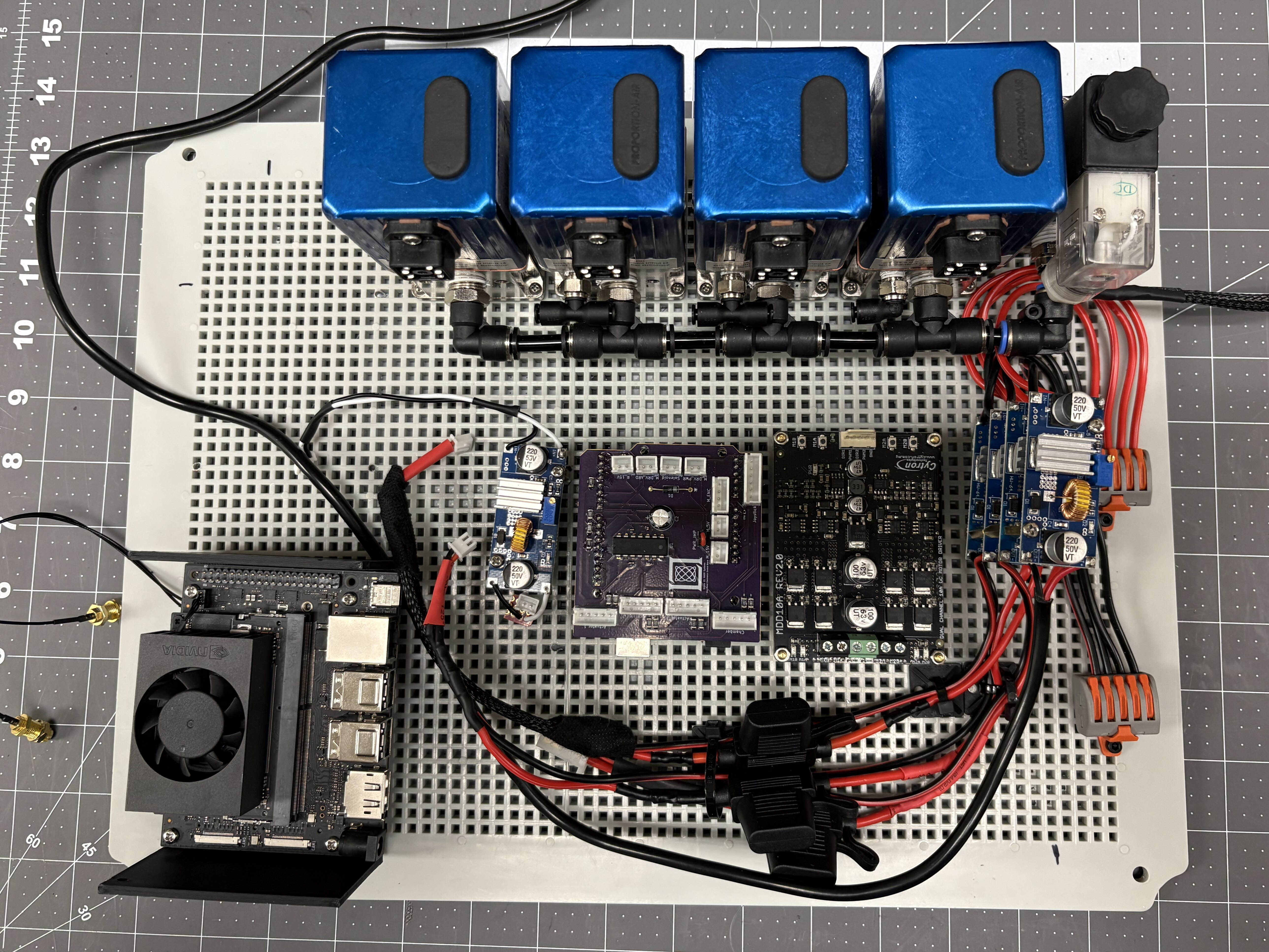
Mount the DC Motor Driver, Arduino Uno Rev3 with custom shield, and the buck converters from the previous step to the plate using adequate fasteners and standoffs.
Step 4: Electrical connections
Continue with Wiring → Section 1. Once complete, come back to do step 5.
Step 5: Install external elements
Required components
| Item | Qty |
|---|---|
| 1/4” Pipe Nipples, 3” Long | 5 |
| 1/4” Push-to-Connect OD x 1/4” NPT Female | 3 |
| 1/2” Push-to-Connect OD x 1/4” NPT Female | 1 |
| 1/4” NPT Female, Quick Connect Air Coupler | 1 |
| 6-pole Receptacle Connector | 1 |
| Wireless NIC Module Antennas | 2 |
| One-way valve, 1/4” NPT Female x 1/4” NPT Male | 1 |
| 1/4” Push-to-Connect OD x 1/4” NPT Male | 1 |
| Through-wall Connector, 1/4” Push-to-Connect OD x 1/4” NPT Female | 1 |
| 1/4” Push-to-Connect OD Wye | 1 |
| 1/4” OD to 1/8” OD Push-to-Connect Adapter | 1 |
Procedure
-
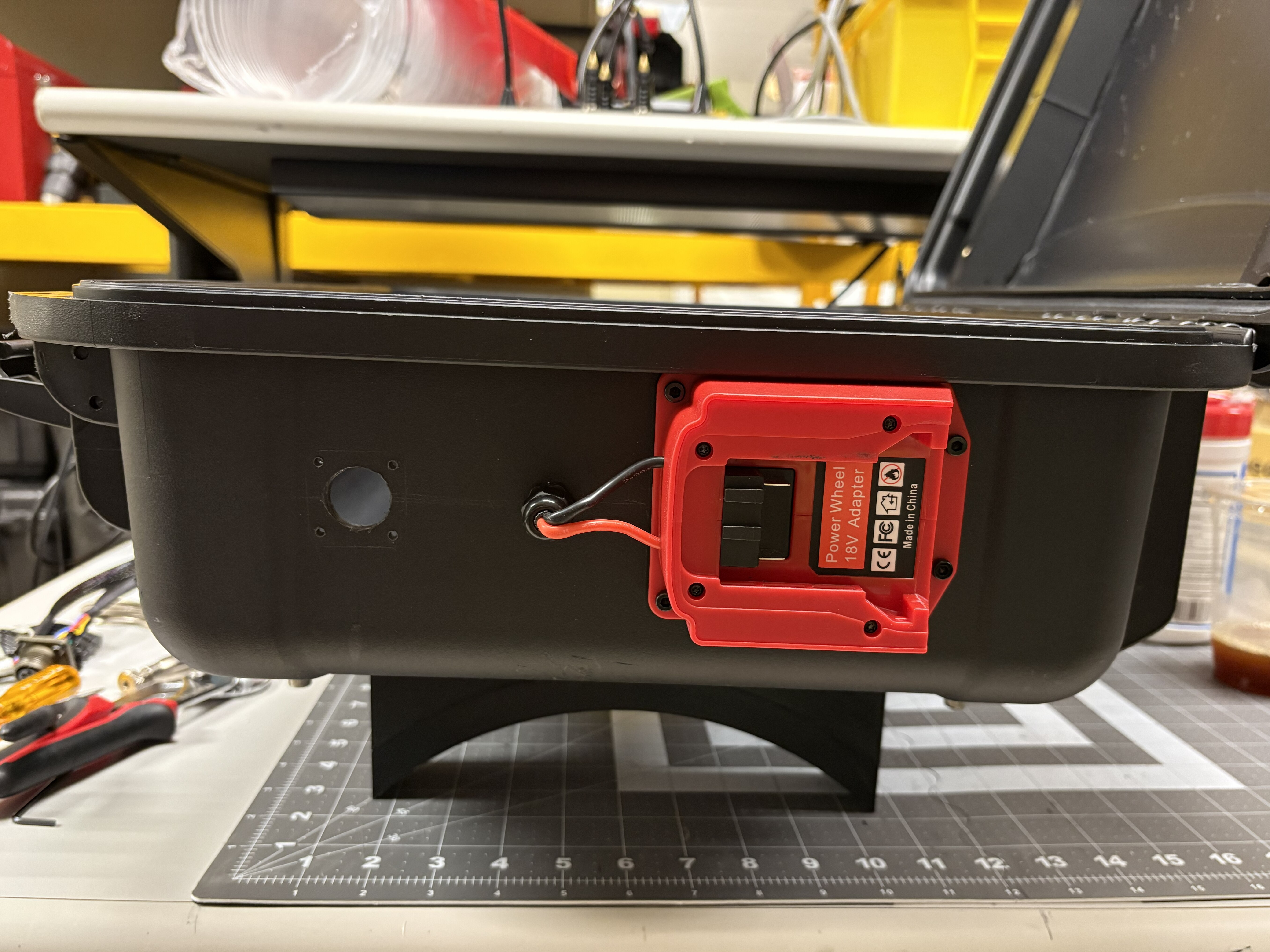
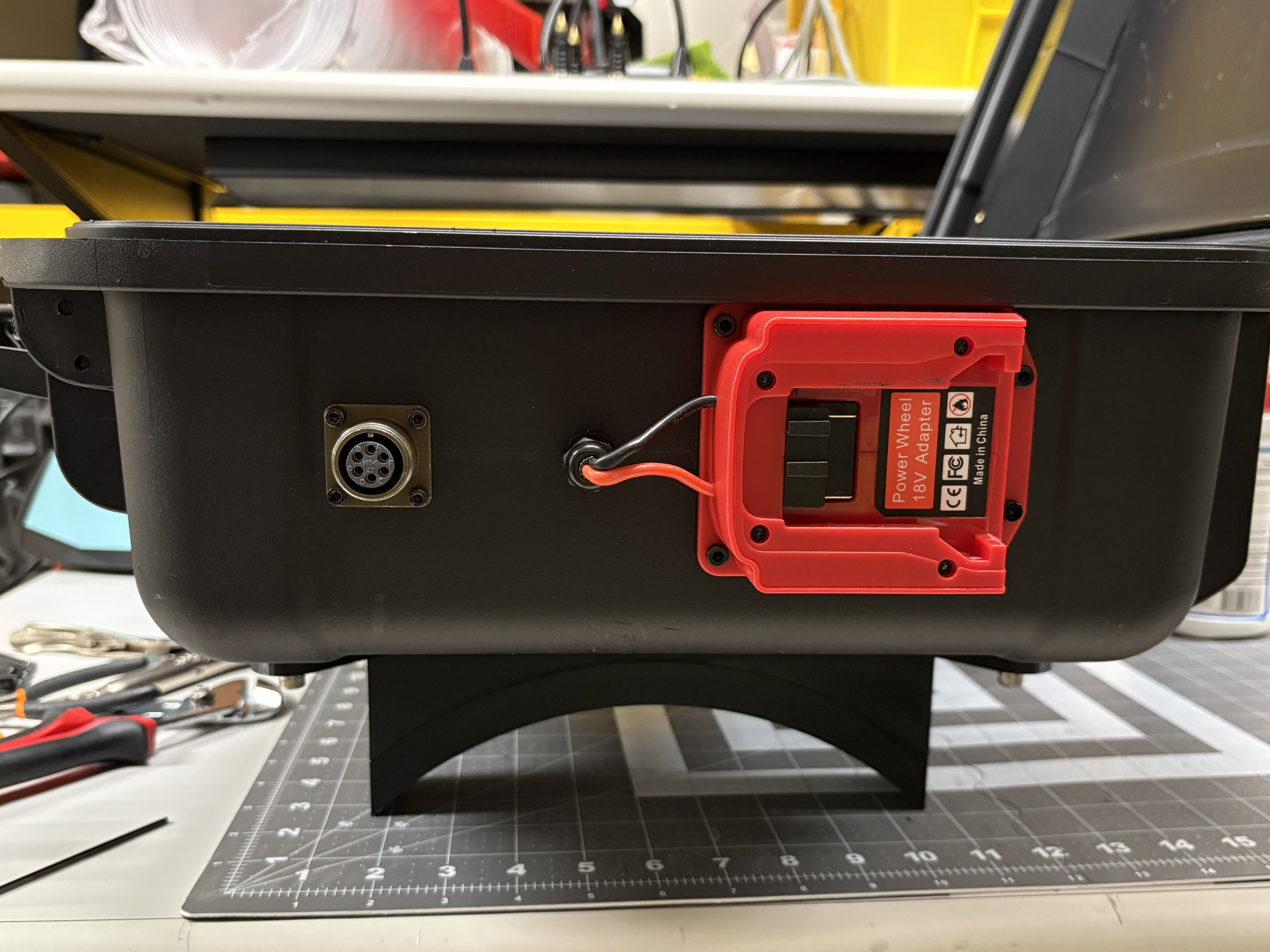
Drill a 3/4” hole about 2” away from the cable gland next to the battery. Insert the 6-pole receptacle connector in the hole, and mark down the mounting hole positions. Drill them out.
-
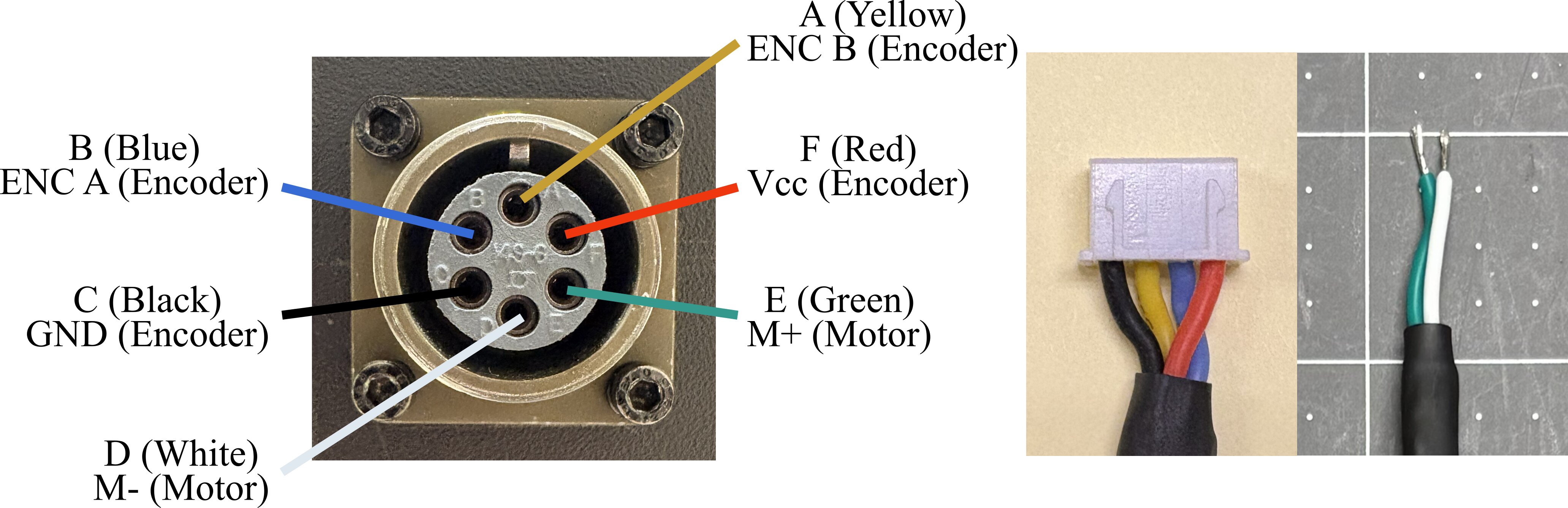
Solder 4-22 AWG stranded wires (about 12” long each) and 2-22 AWG stranded wires (about 10” long each) to the receptacle connector. Follow the wiring shown below to have wires in the right order on the connectors. This is the connector used to connect the robot base motor and encoder to the arduino and motor driver. Depending on how these are wired in the robot base, you may need to switch the wiring on this receptacle.
-
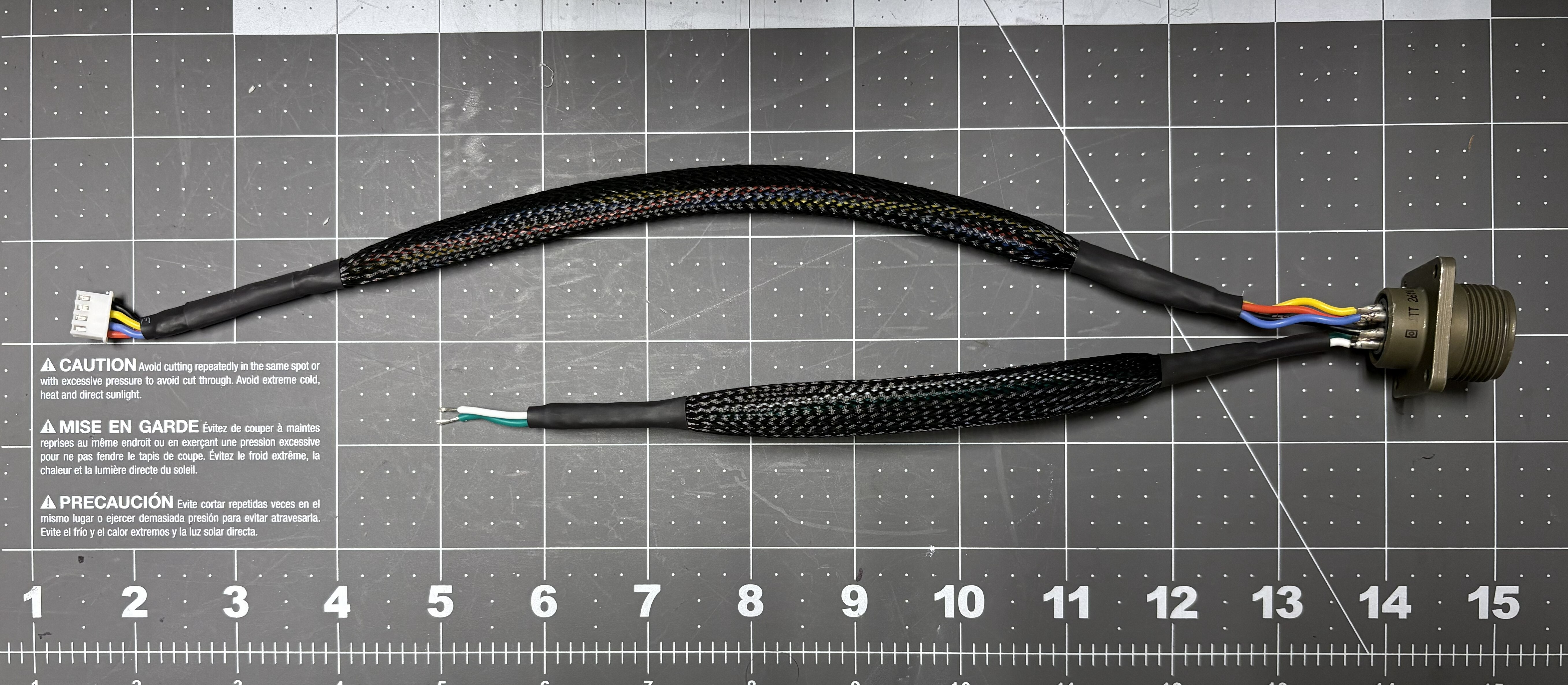
Cover the 4 longer wires with braided wire sleeving and insert two heat shrink tubing section of about an inch each. On the free end of the wire, crimp the ends and install a 4-pin JST-HX male connector (see picture above and below). Cover the 2 shorter wires in the same way, but leave the ends free and tin them.
-
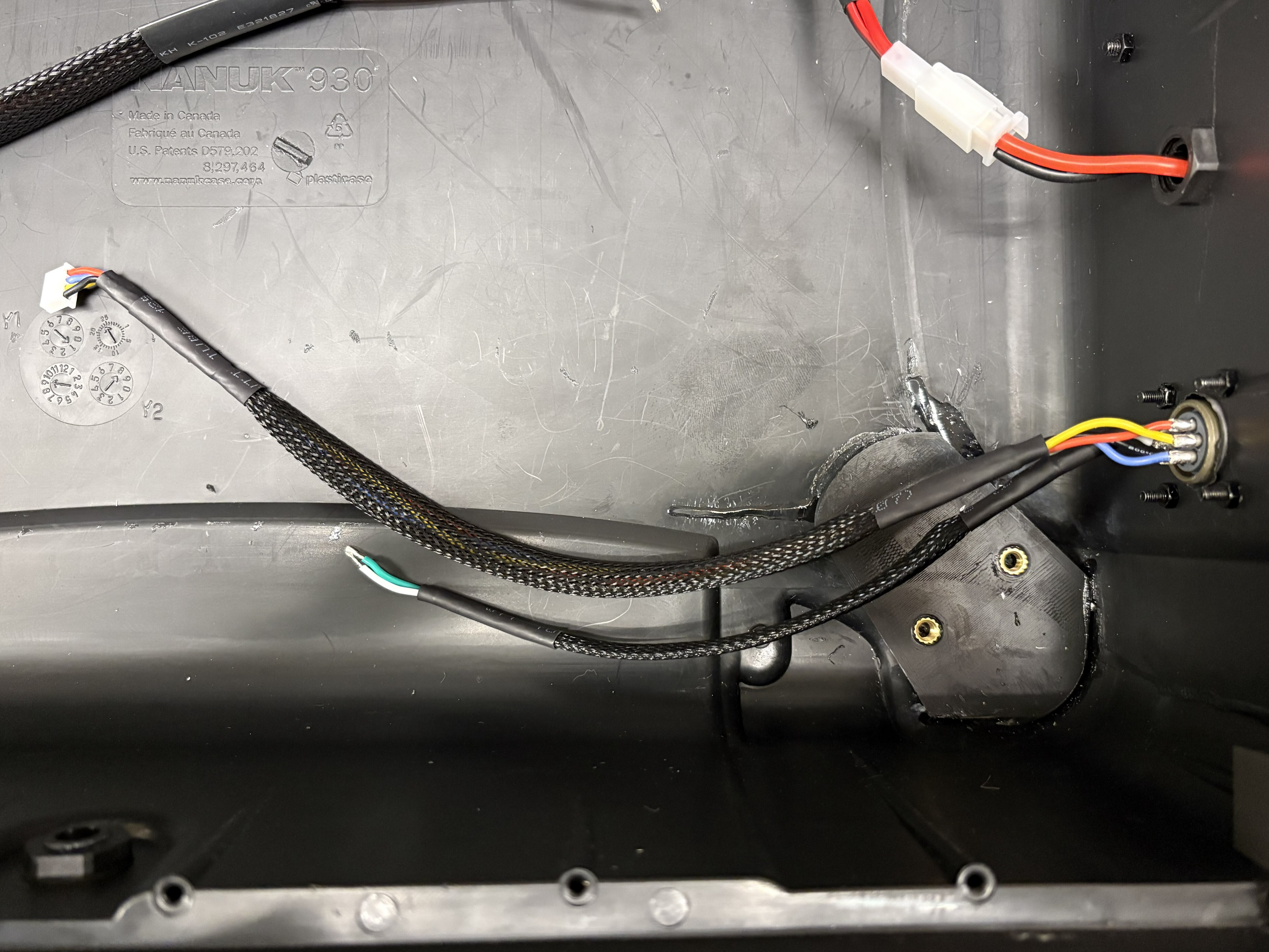
Mount the receptacle to the case using appropriate fasteners.
-
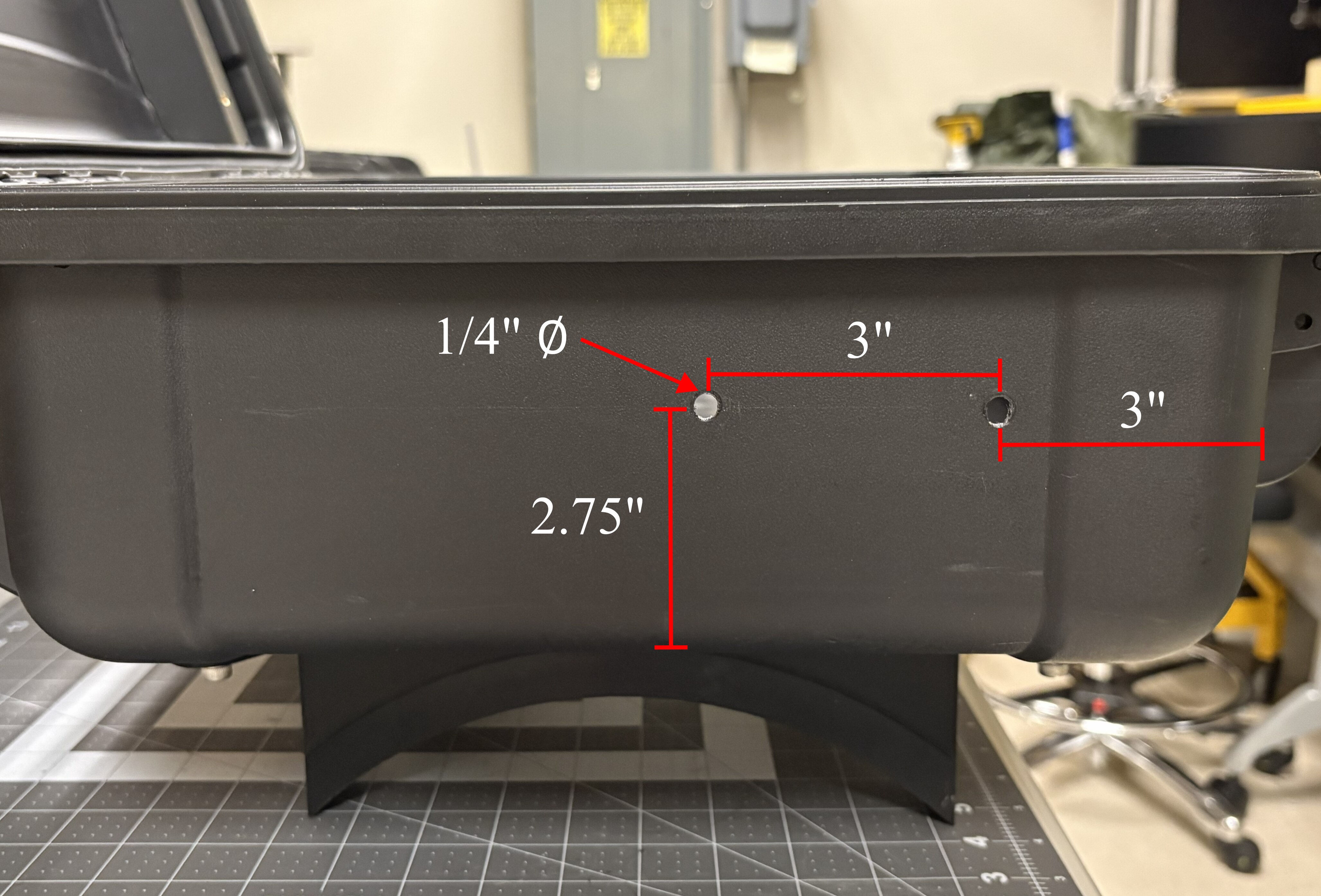
On the left side of the case (the one that is untouched at this point), drill two holes to mount the wifi antennas.
-
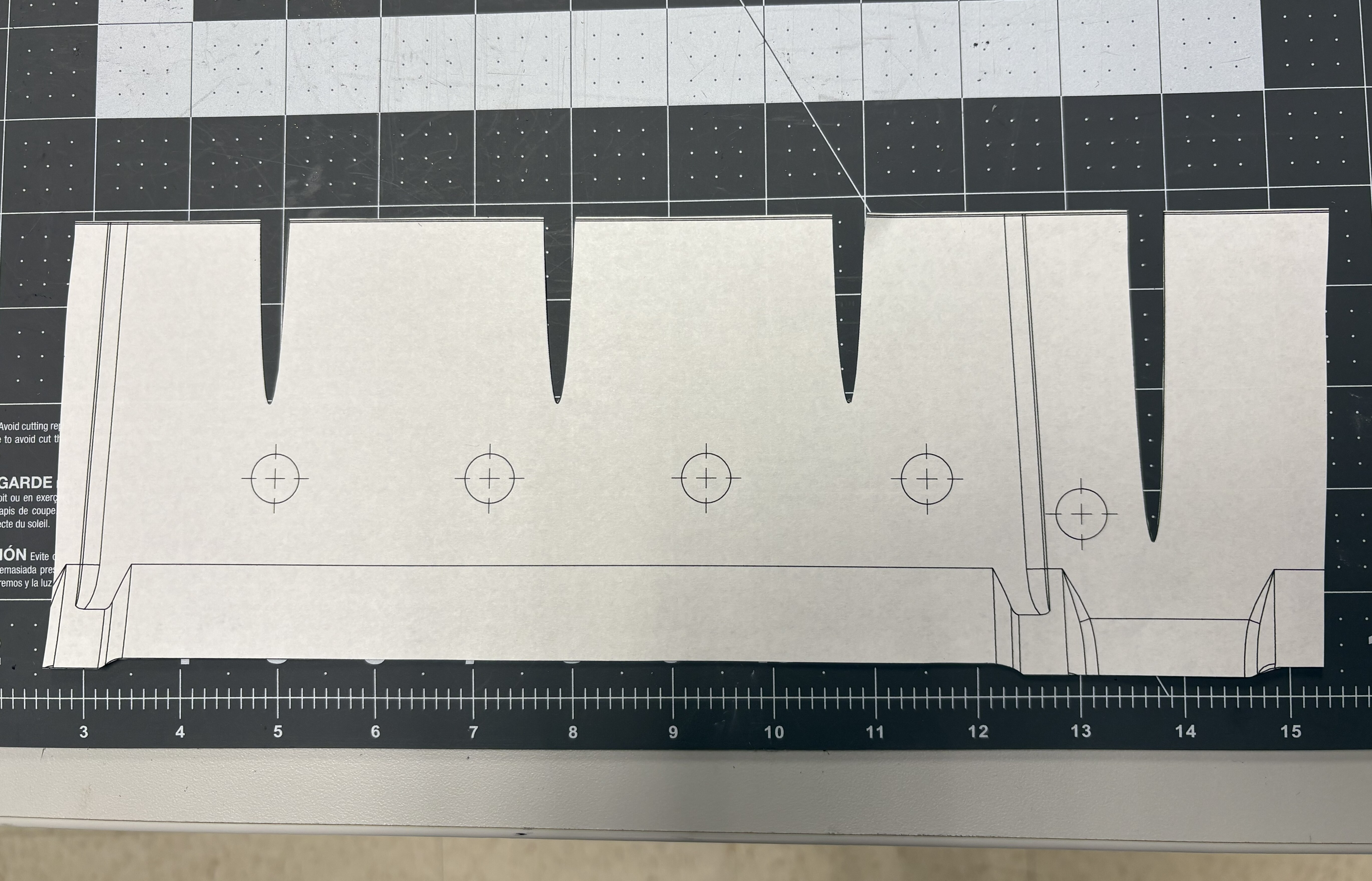
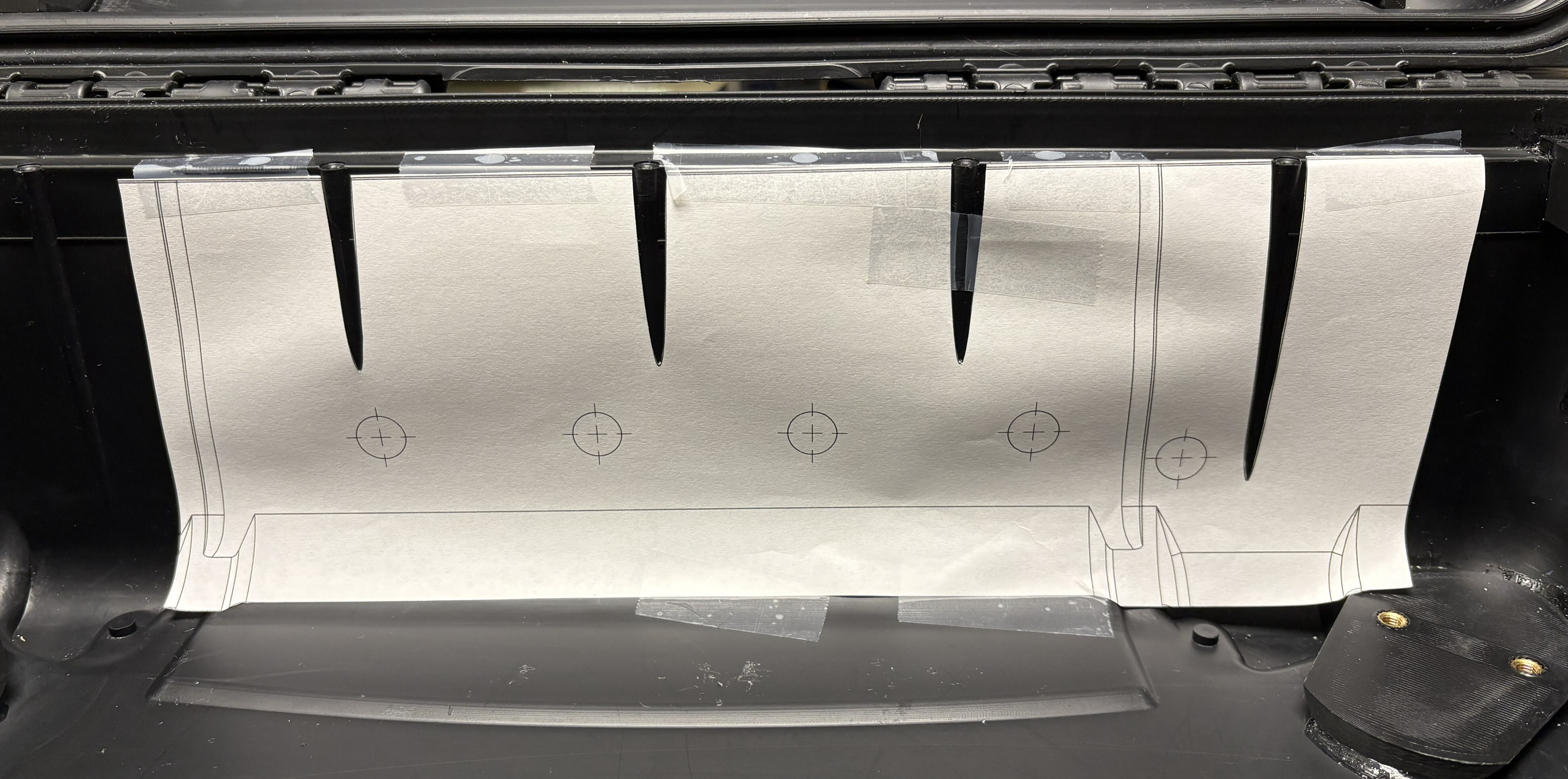
Print the hole pattern provided in the CAD section, and cut it with scissors as shown below. These cuts help with alignment inside the case. Tape the cutout to the case in the inner, longer side by the hinge.
-
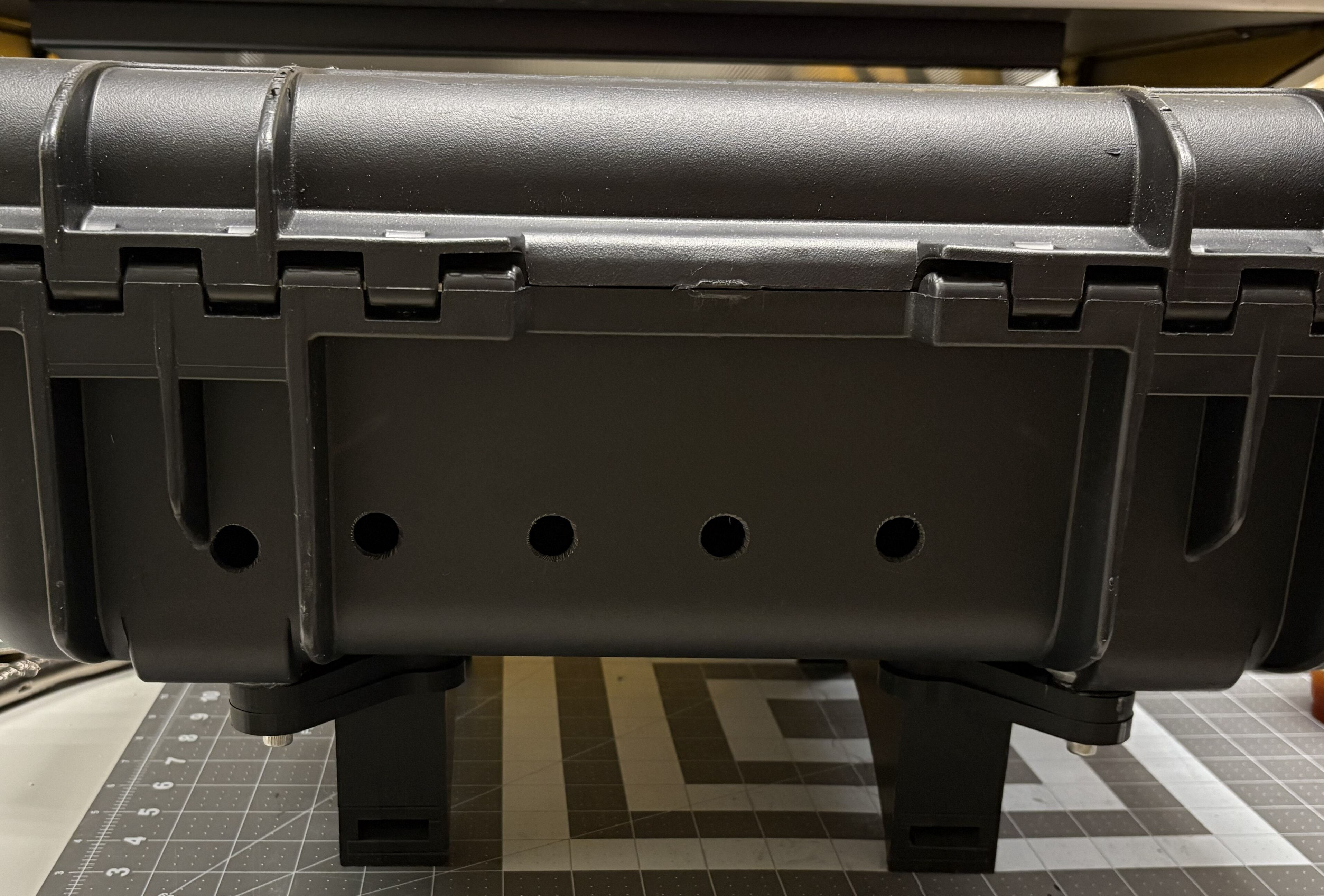
Drill the holes using 1/2” hole saws. Adjust the size as needed with a deburring tool so that a 1/4” Pipe Nipple can pass through it.
-
Mark down a dot 1.5” from the bottom and 1” from the right edge (see below) to drill another (9/16”) hole to the right of the holes cut in the previous step.

-
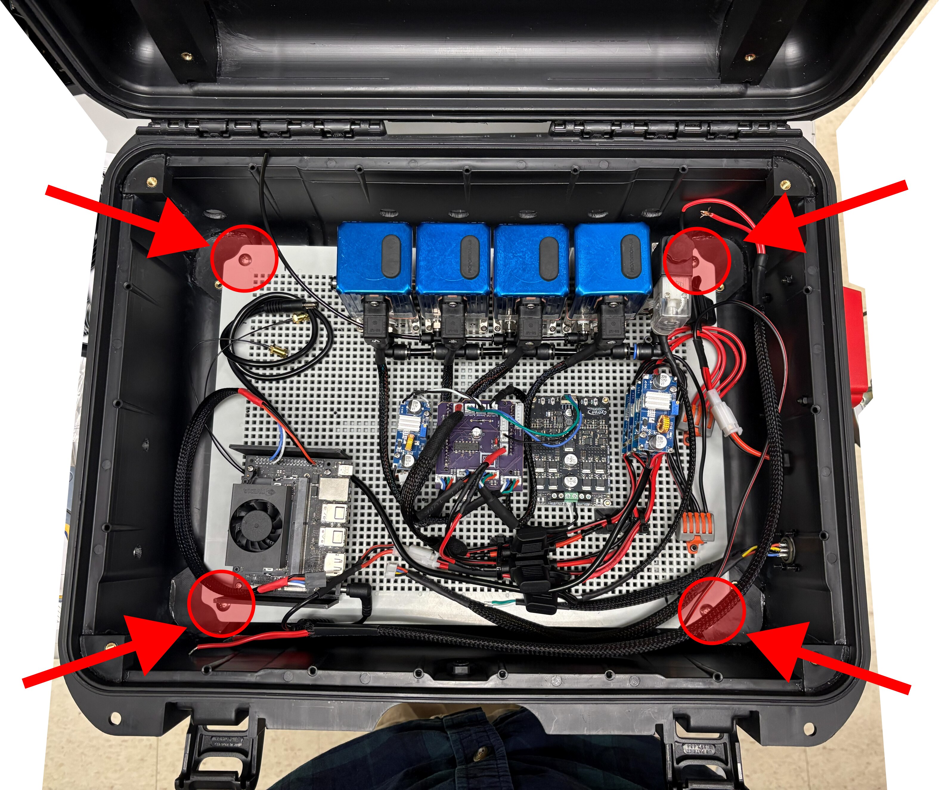
Once all holes have been drilled, install the mount plate in the case. Secure with fasteners.
-
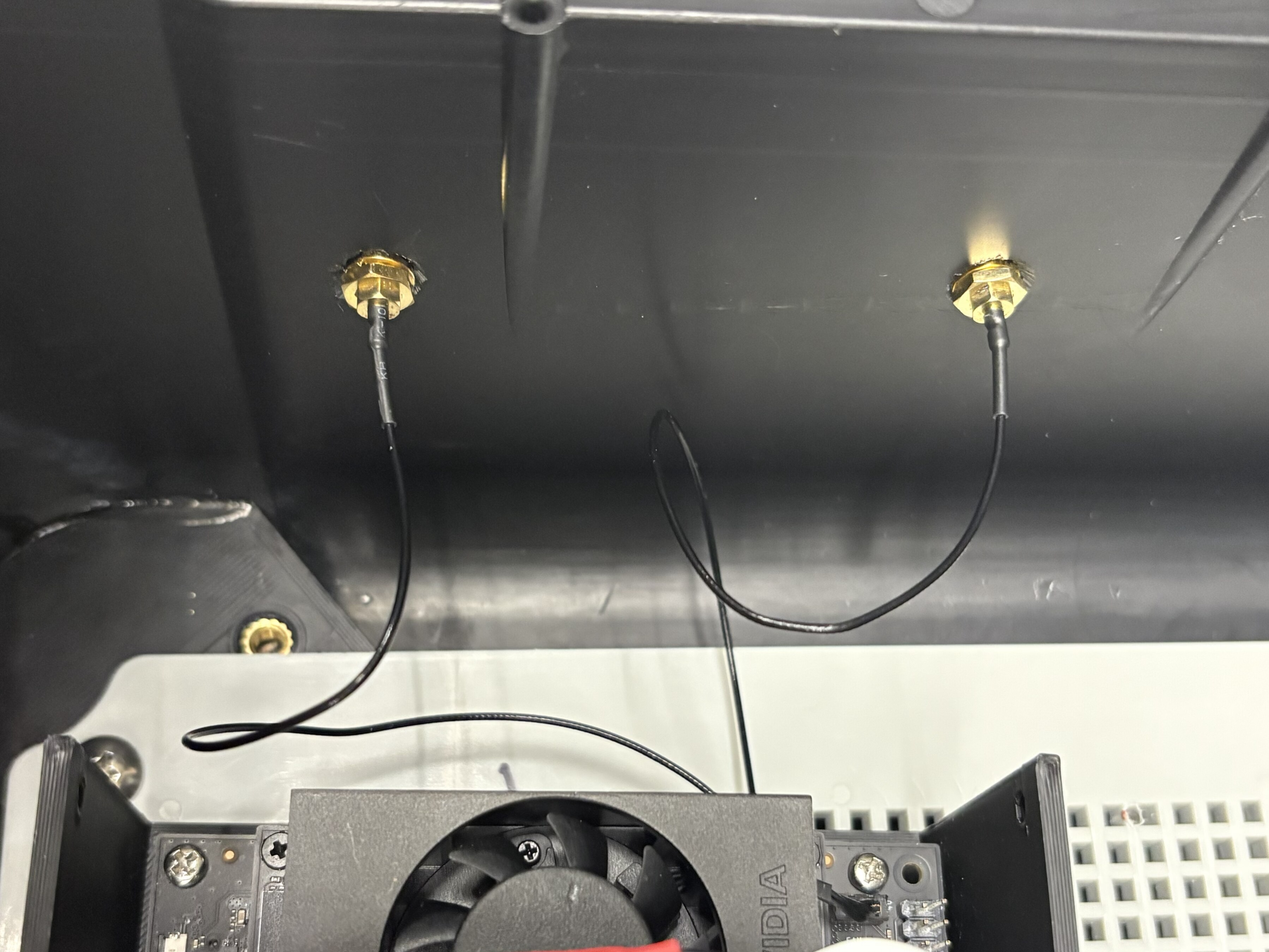
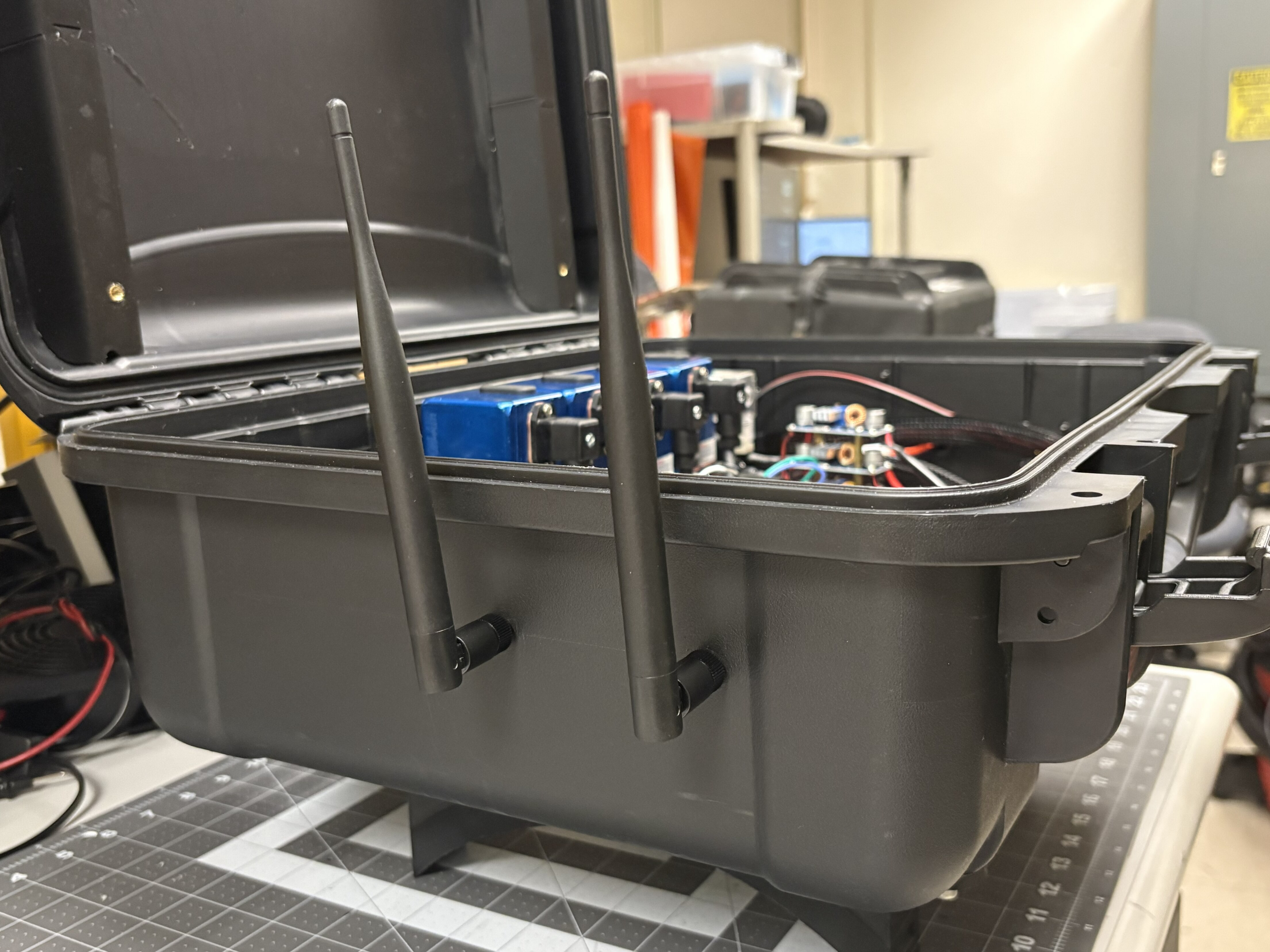
Install the antennas by mounting the connectors in the holes and screwing the antennas in.
-
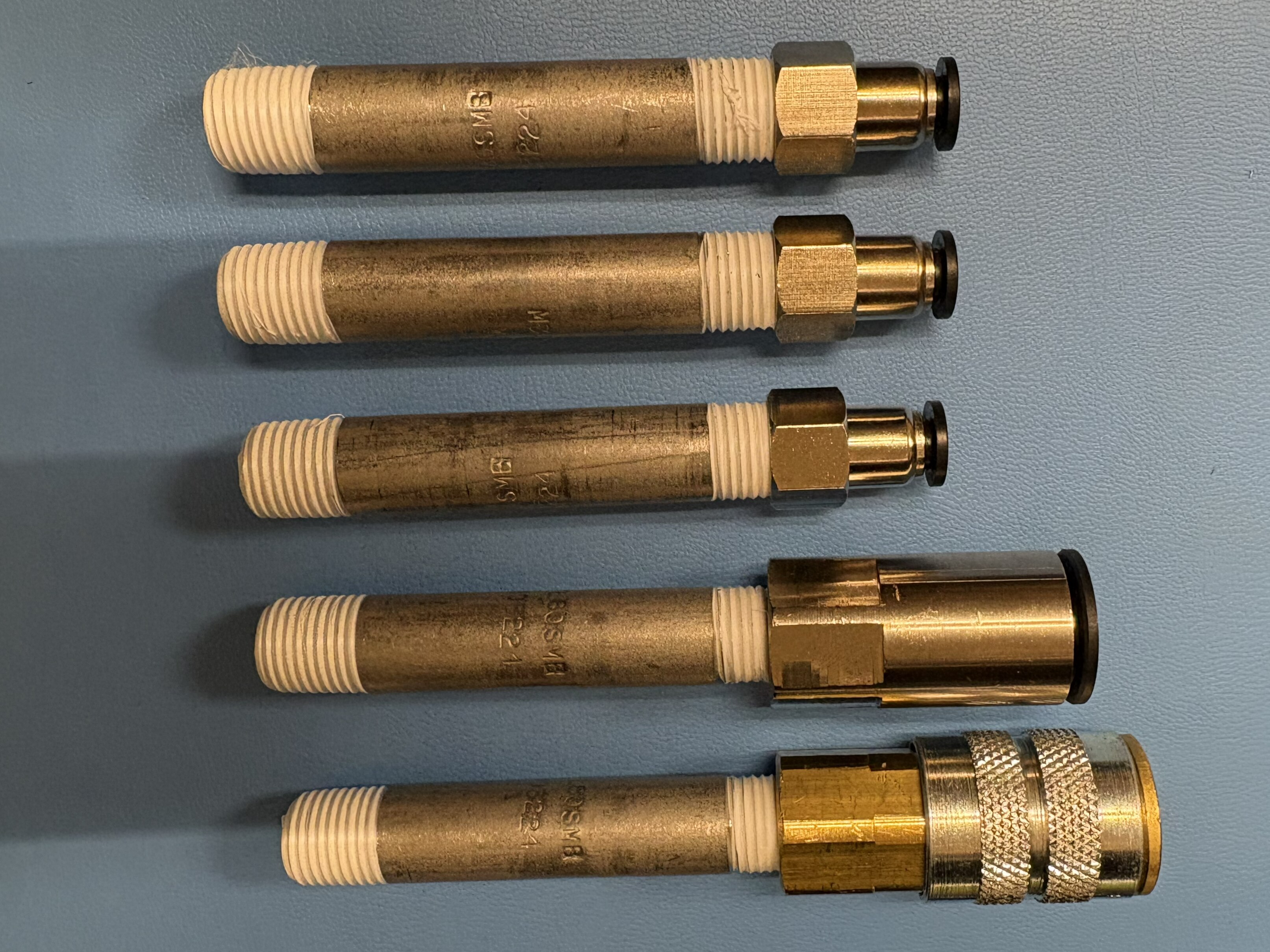
Apply teflon tape in the pipe nipples, and install the connectors/adapters on one side: 3 with 1/4” Push-to-Connect OD x 1/4” NPT Female, 1 with 1/2” Push-to-Connect OD x 1/4” NPT Female, and 1 with 1/4” NPT Female, Quick Connect Air Coupler.
-
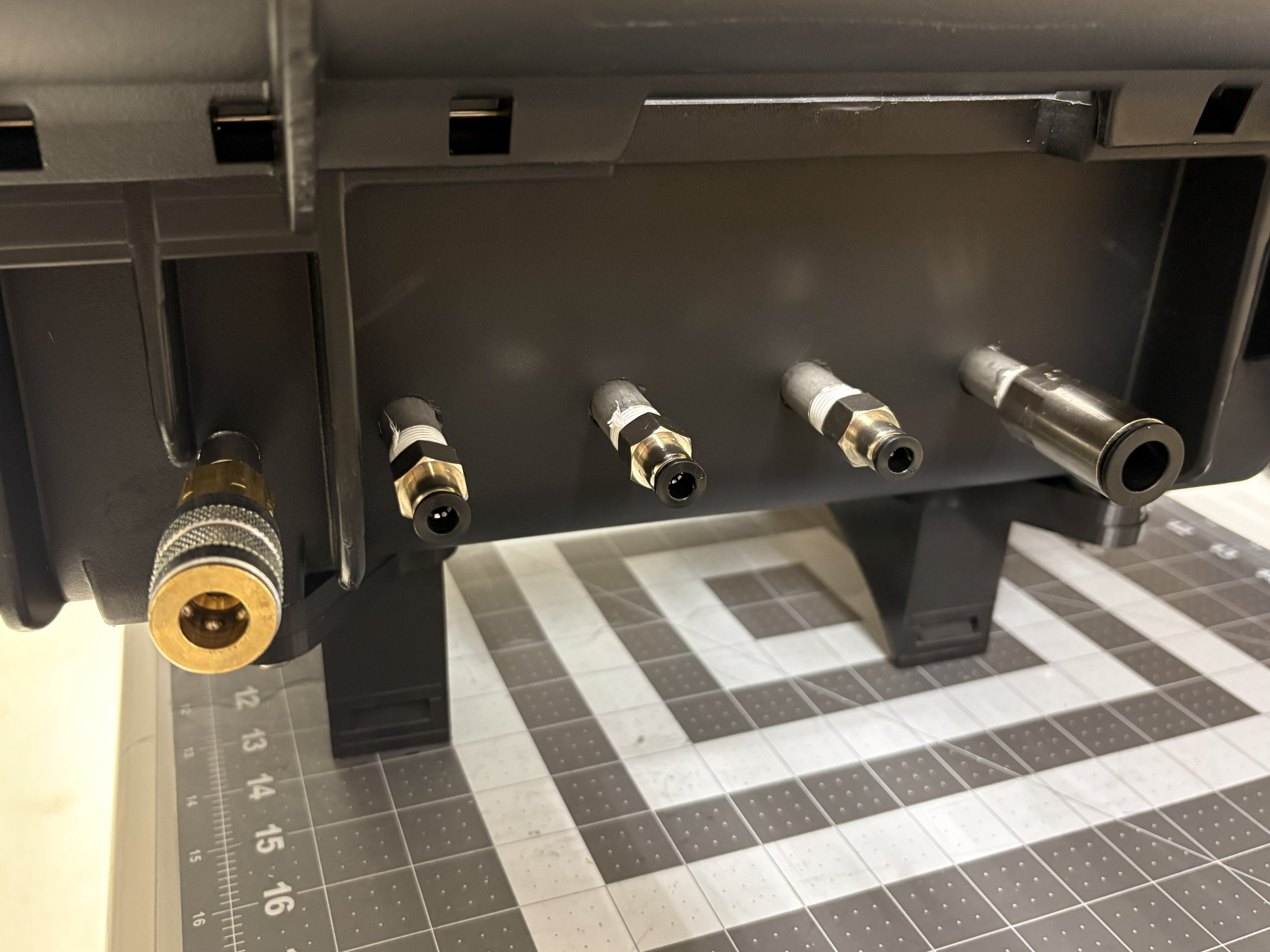
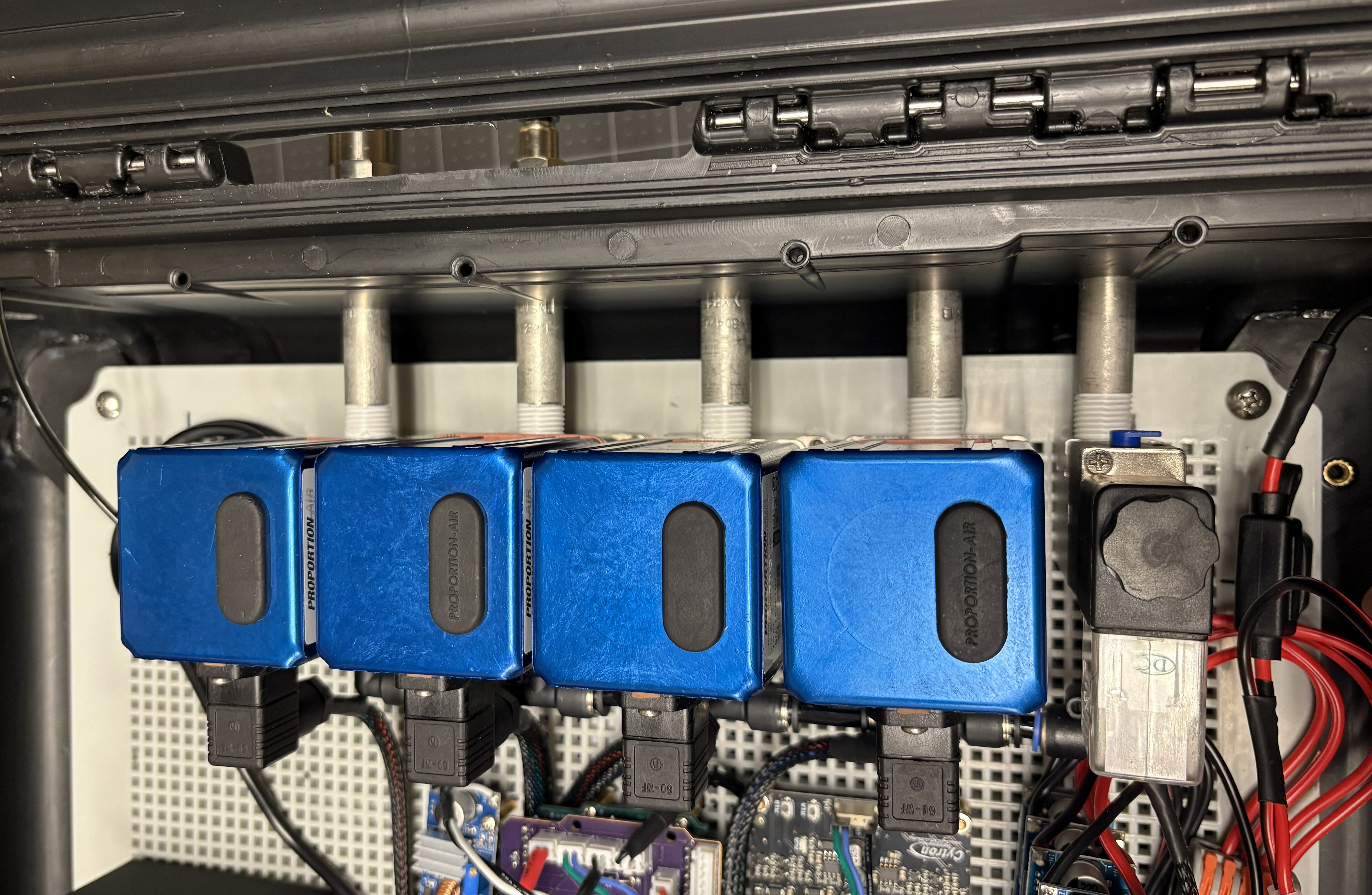
Pass the pipe nipples through the holes from the outside. Screw them into the QB3 pressure regulators and solenoid following the order shown below.
-
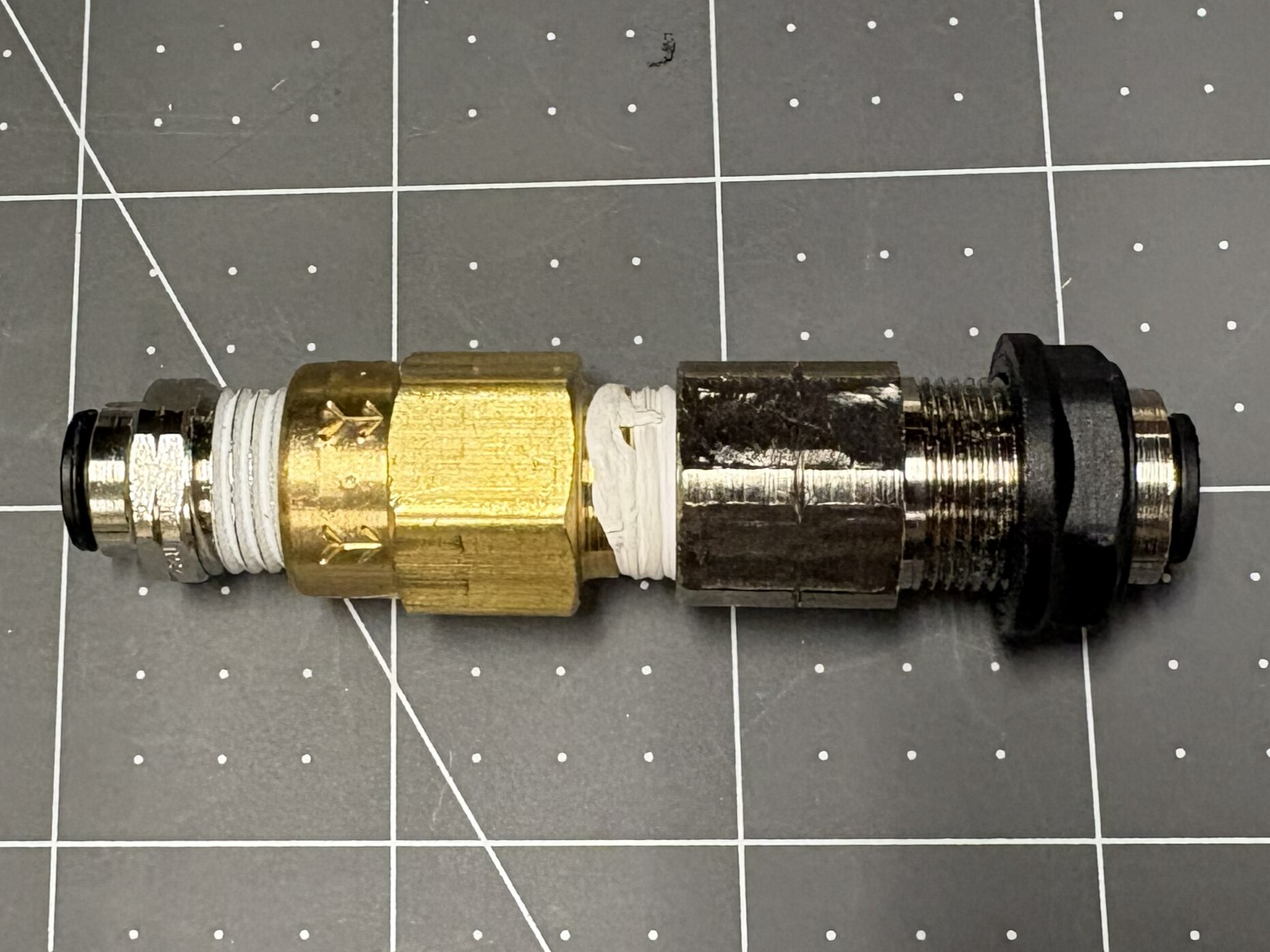
Connect the one-way valve, the push-to-connect adapter, and the push-to-connect through-wall connector as shown below.
-
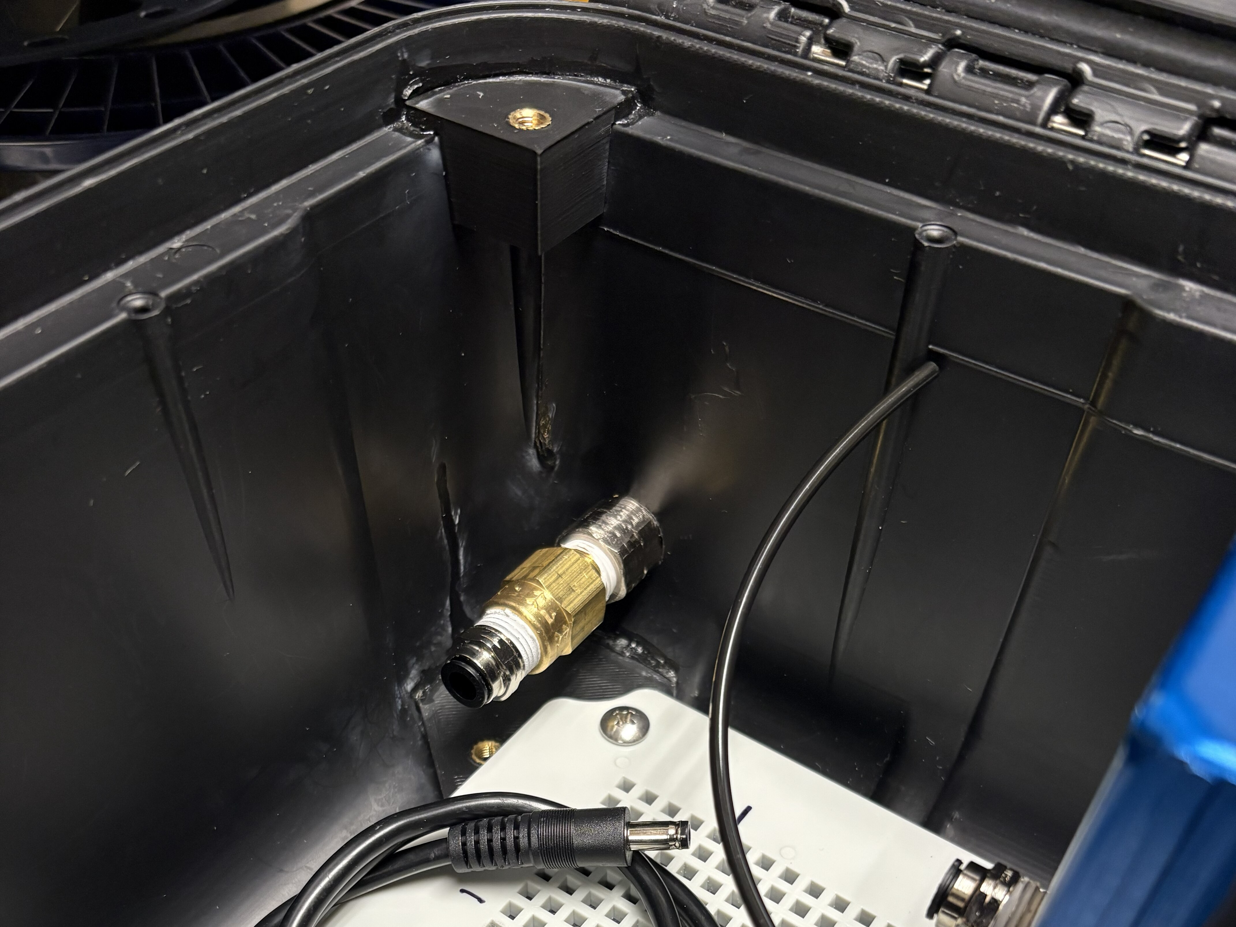
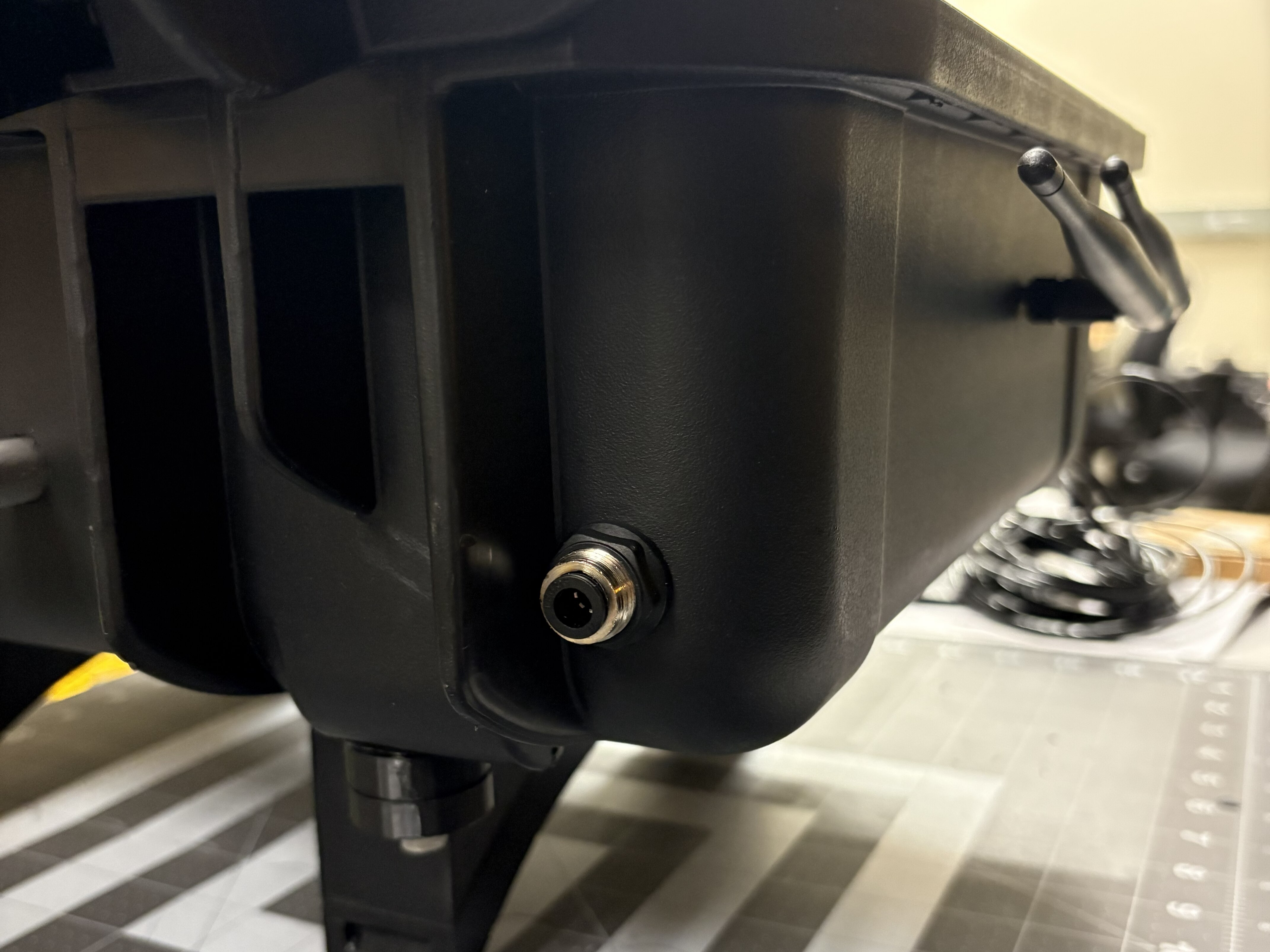
Install the assembled adapter in the bottom hole made in step 8.
-
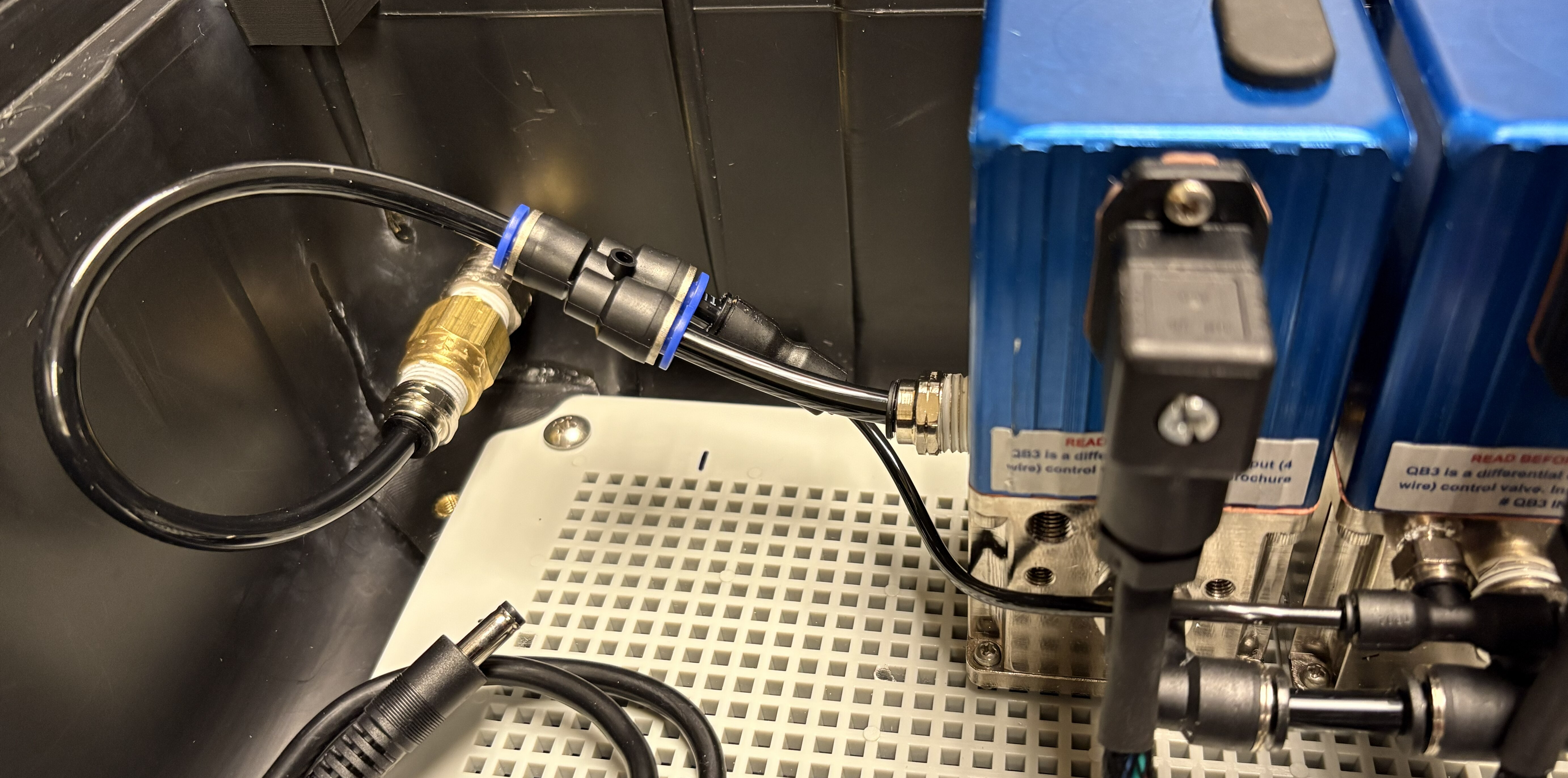
Connect the exhaust lines of the QB3s using a 1/8” to 1/4” adapter and a Wye to the installed one-way adapter. This will be the exhaust line.
Step 6: Install communication interfaces
Required components
| Item | Qty |
|---|---|
| USB Connector Panel-Mount | 2 |
| USB 3.0 Cable 1ft Long, A-to-A, Male-to-Male | 2 |
| DisplayPort to HDMI Cable, 3ft Long | 1 |
| HDMI Connector Panel-Mount | 1 |
| RJ45 Connector Panel-Mount | 1 |
| Ethernet Extension Cable 1ft Female-to-Male | 1 |
| LCD1602 Display Module | 1 |
| Emergency Stop Switch | 1 |
| Push Button Switch | 1 |
| Push Button Cover | 1 |
| Right Angle USB A to USB B male connector | 1 |
Procedure
-
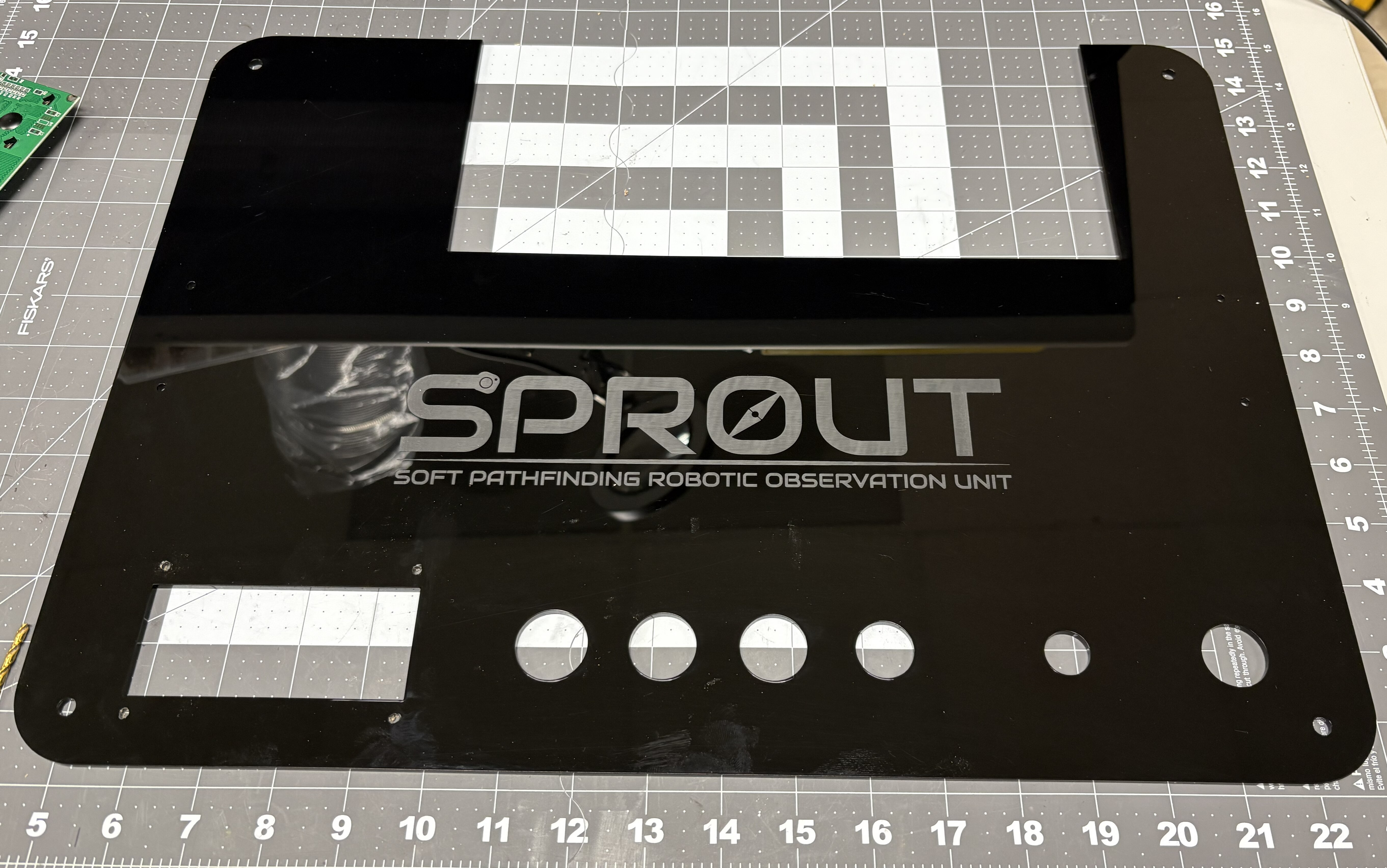
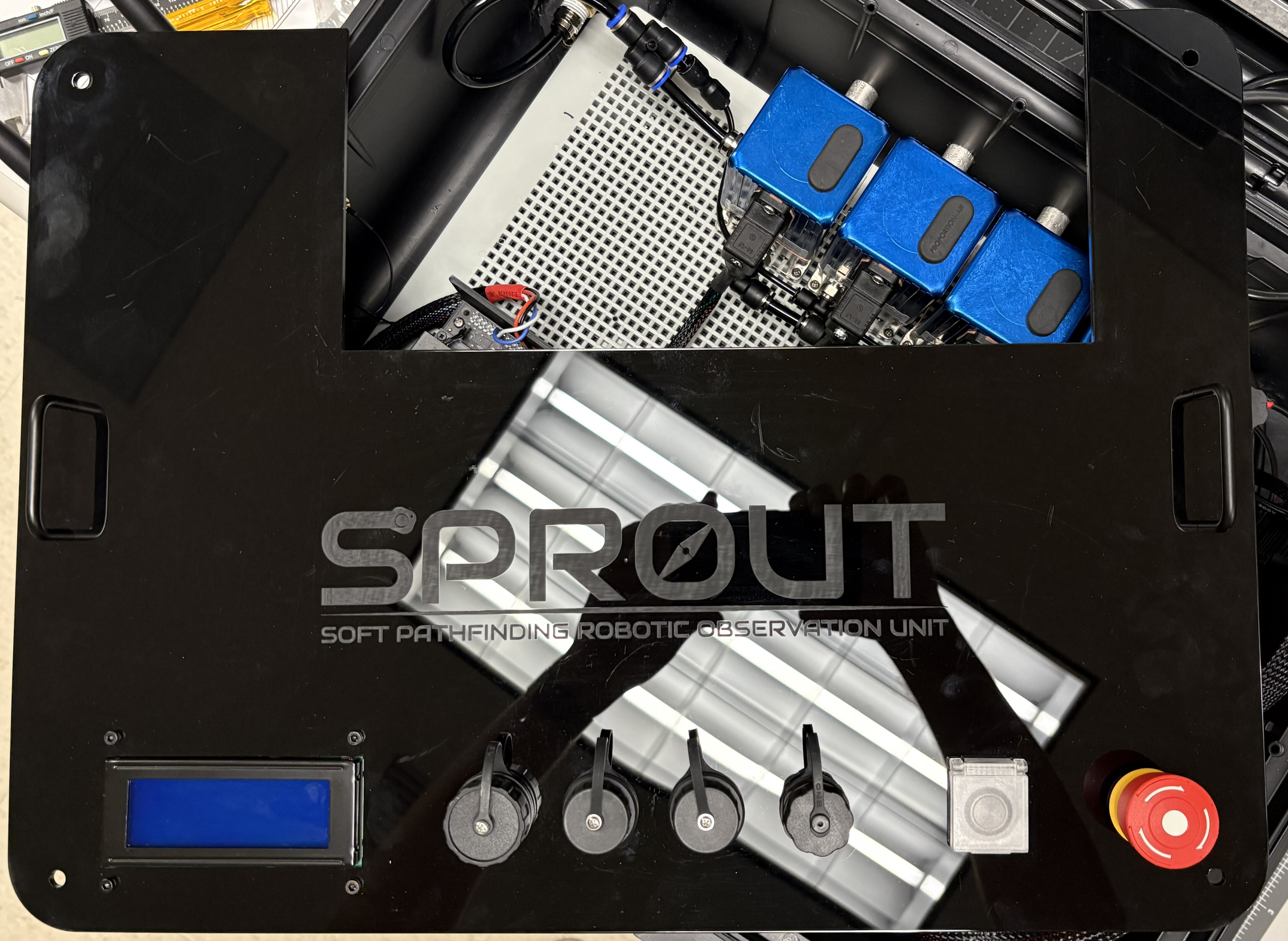
Laser cut an 18x24 3mm acrylic sheet using the pattern provided in the CAD section. Rendering the logo is optional.
-
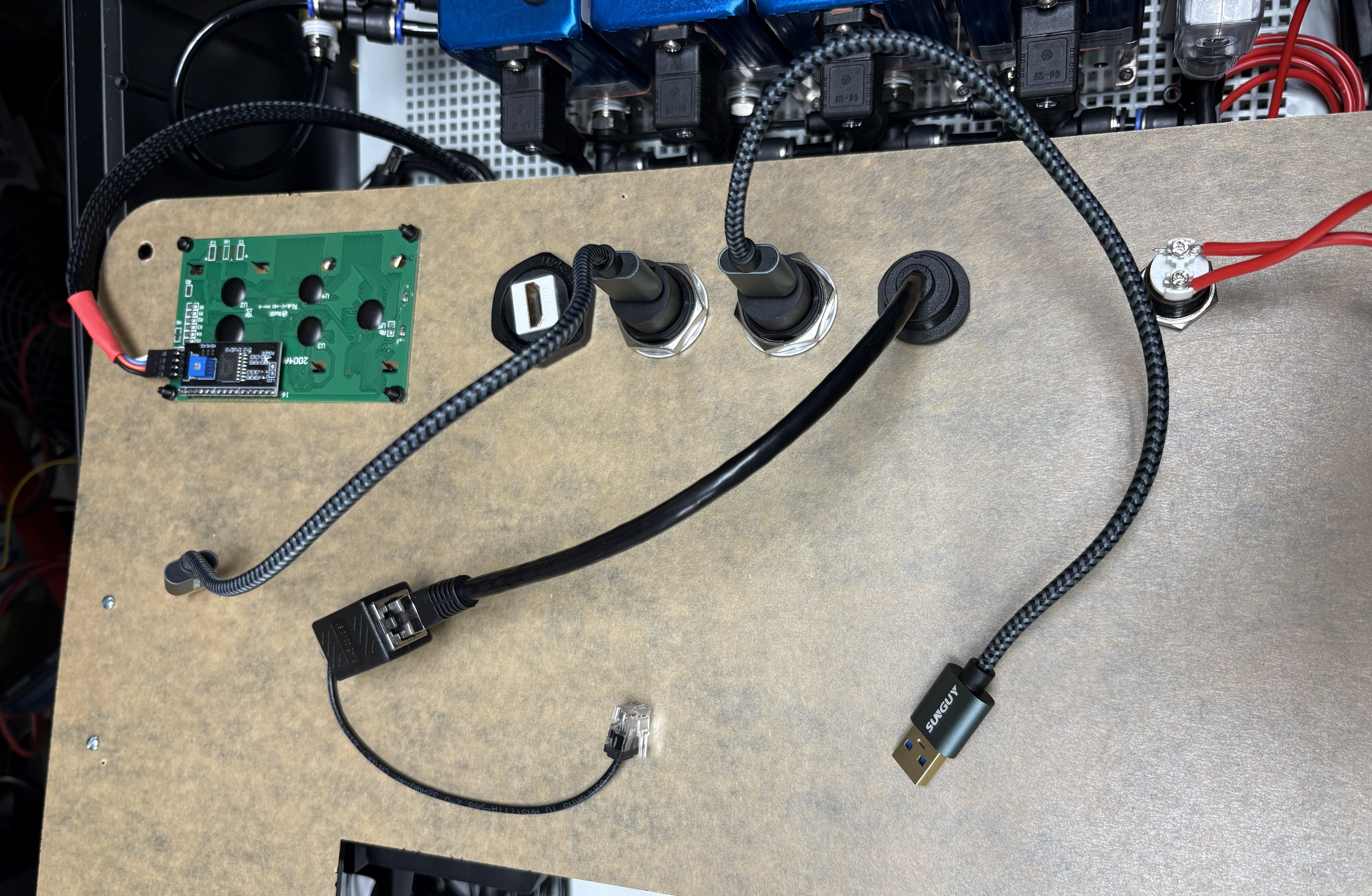
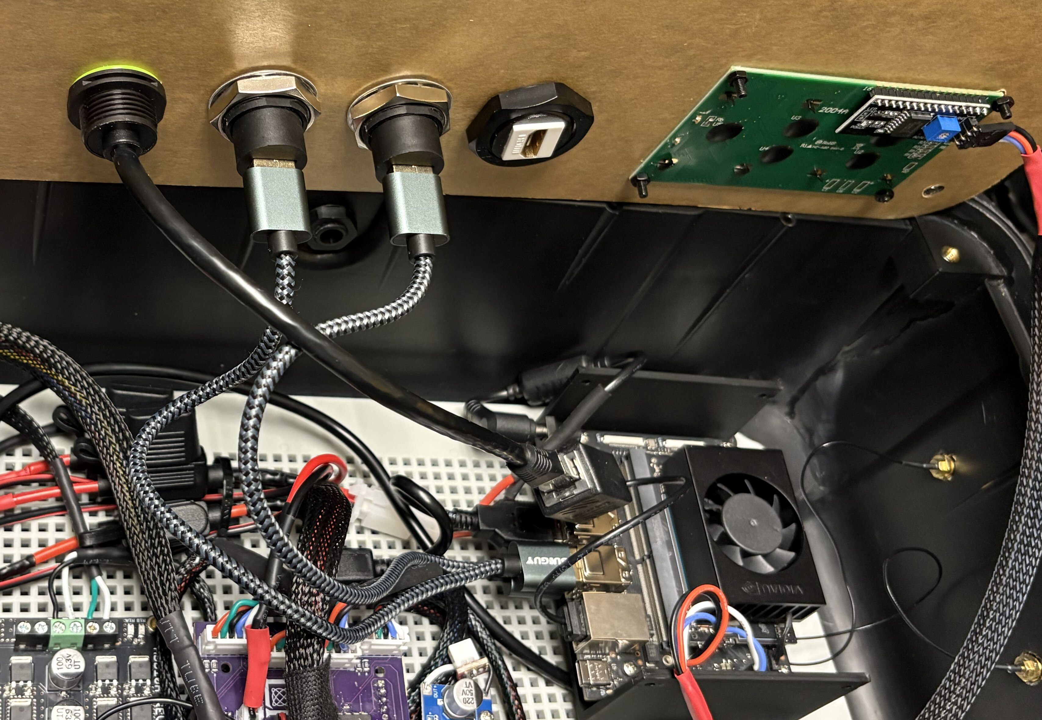
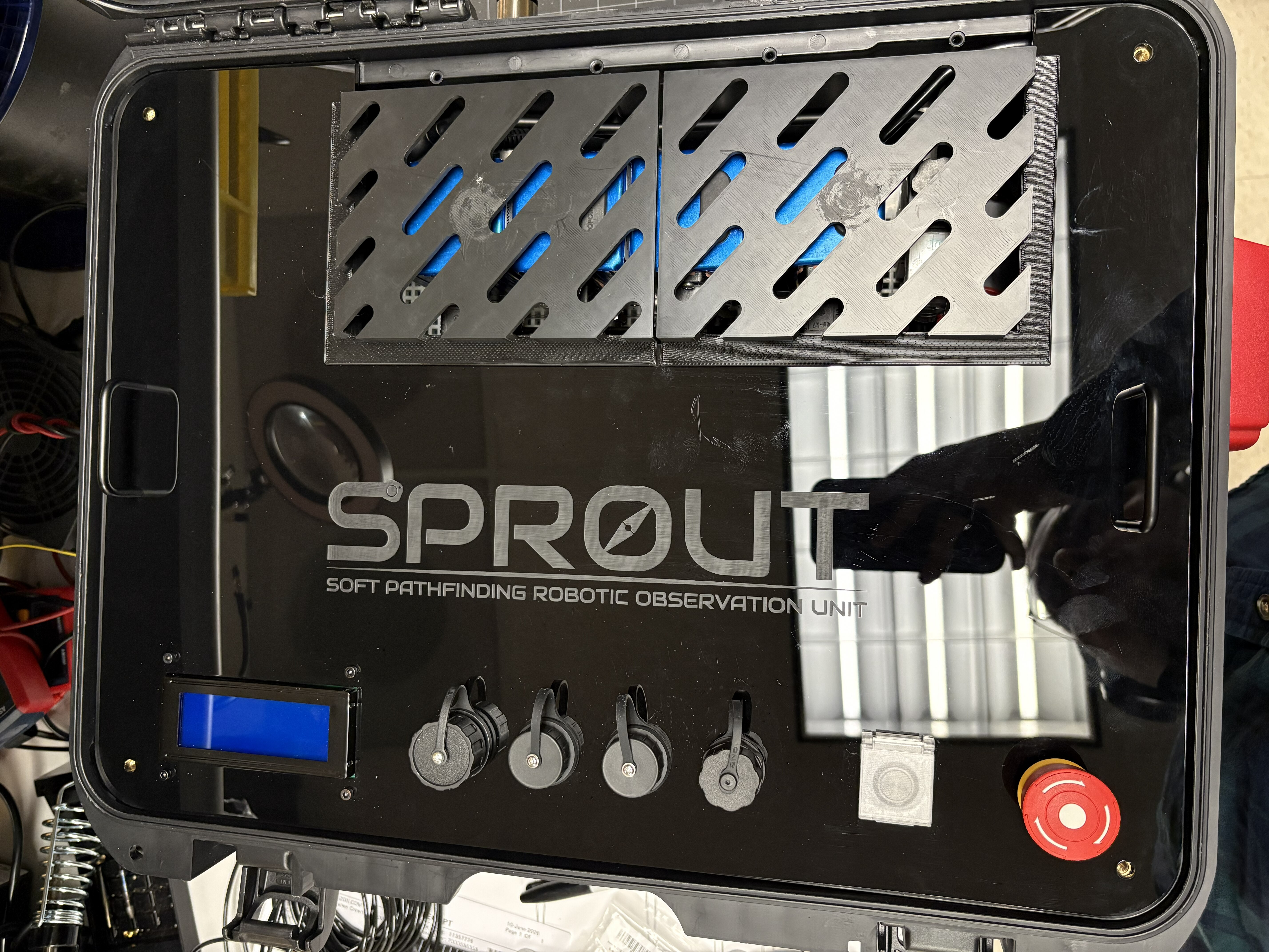
Install the side handles, peripheral connectors, push button (with cover), E-button, and LCD screen as shown. From left to right: LCD screen, HDMI connector, USB-A connector, USB-A connector, Ethernet RJ45 connector, push button with cover, E-button.
-
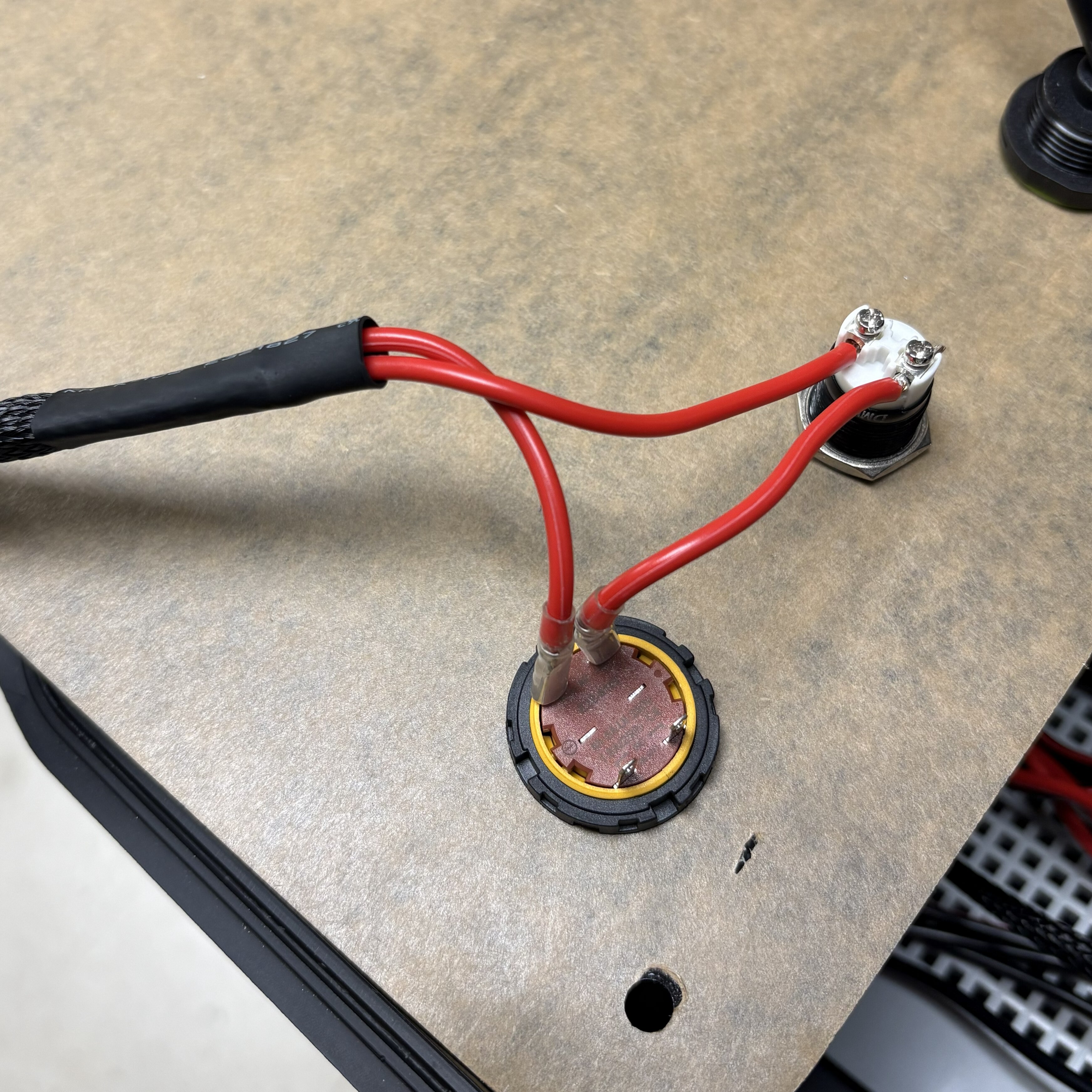
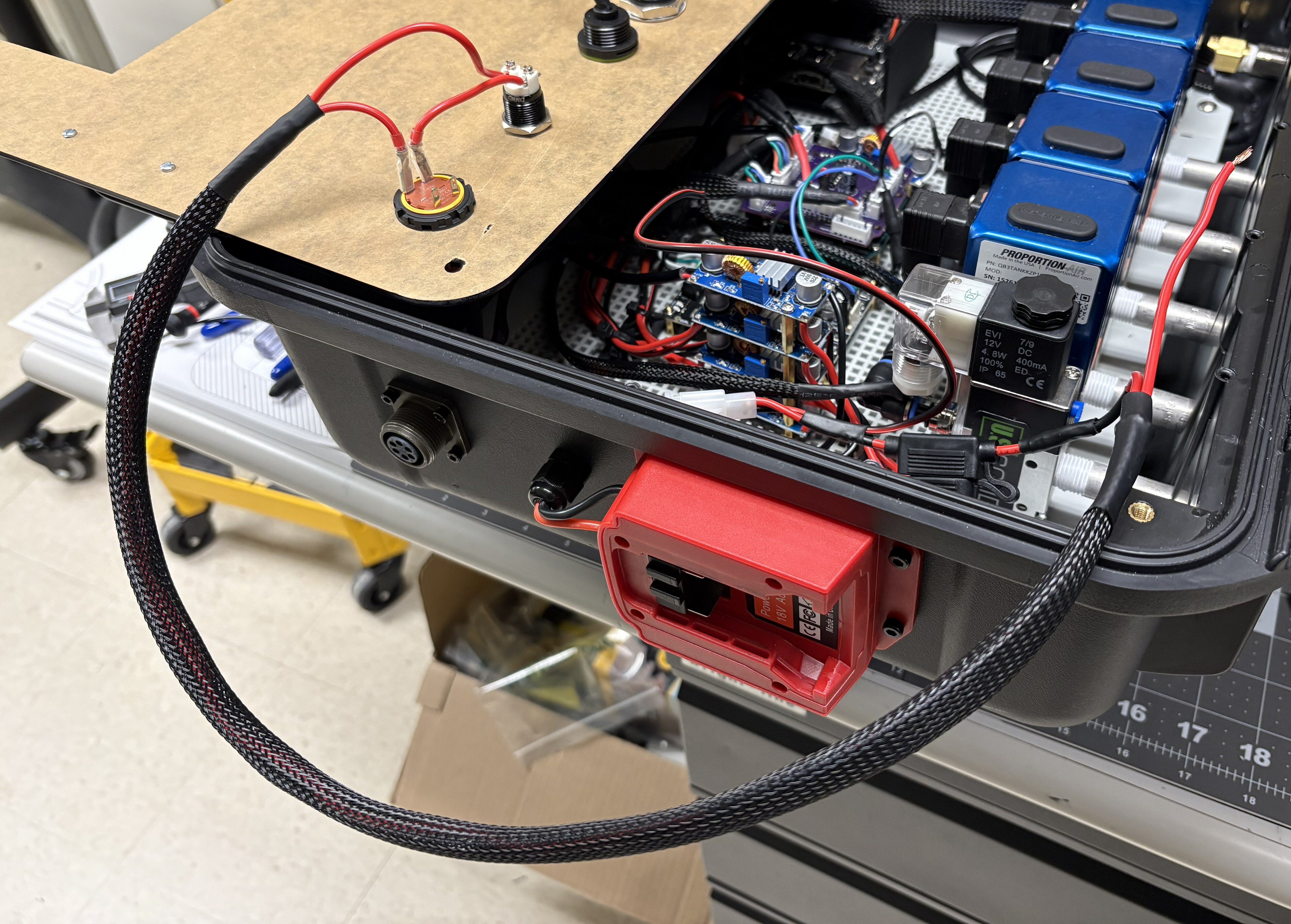
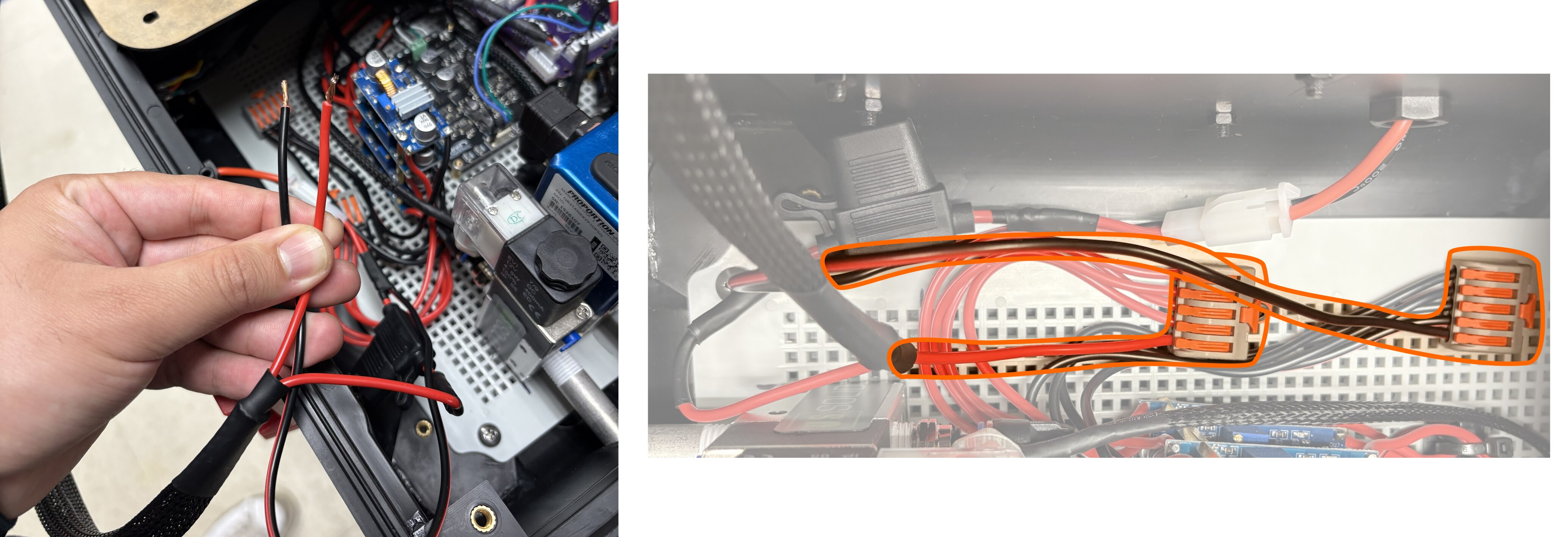
Grab the end of the wires created in Step 2.7 (coming from the battery adapter fuse holder). Identify the cable inside the sleeve that is coming from the fuse holder; connect to the screw-in terminal in the push button. Screw another 3” segment of 16 AWG red wire to the other push button terminal.
-
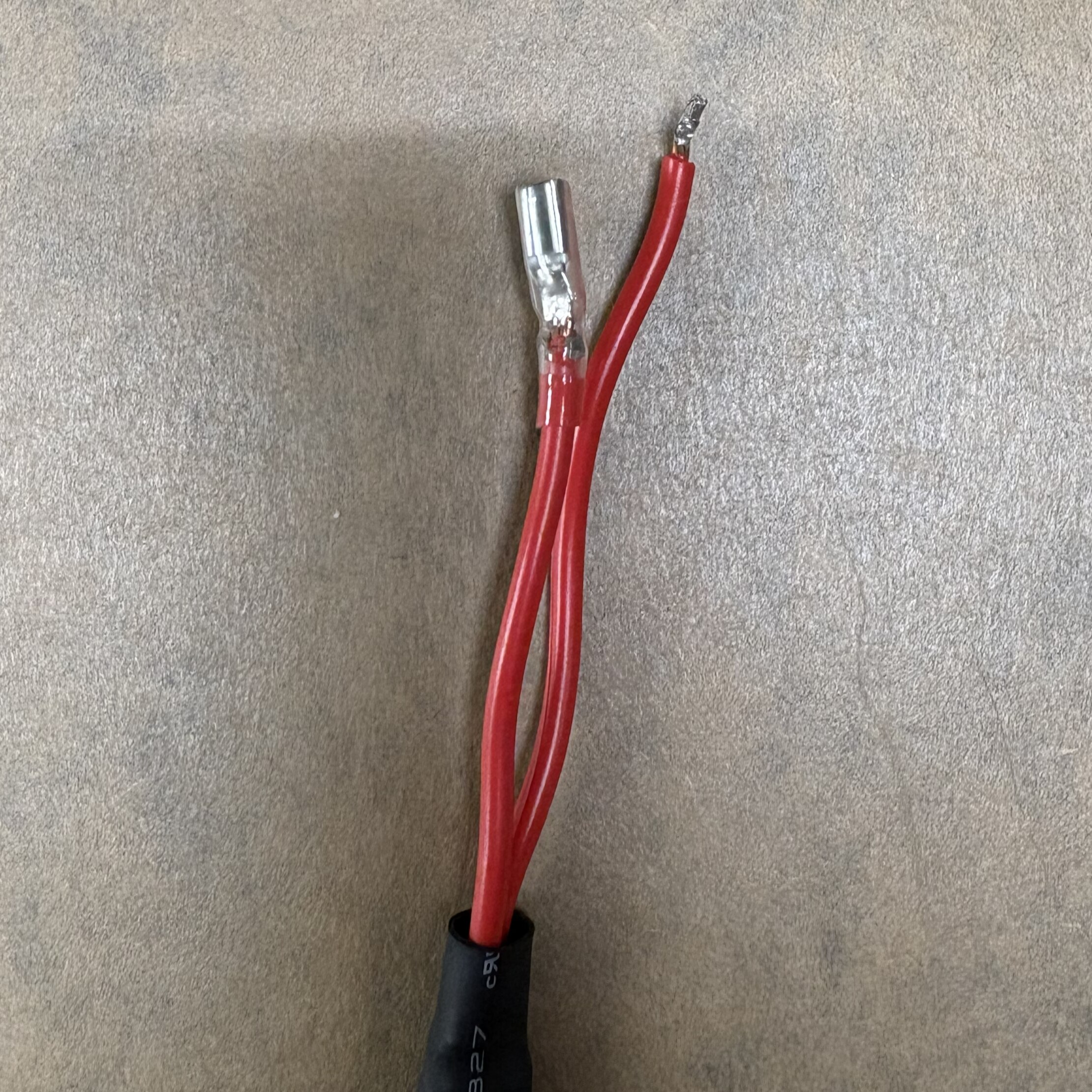
The E-button should come with 2.8mm female spade crimp connectors. Crimp one on the short wire connected to the push button in the previous step, and another on the long wire coming from the sleeve.
-
On the other end of the sleeve, there is a free end on a red wire, and a black wire coming from the battery connector and fuse holder (see Step 2.7). Connect these to the lever connector’s last empty slot (see Step 2.14).
-
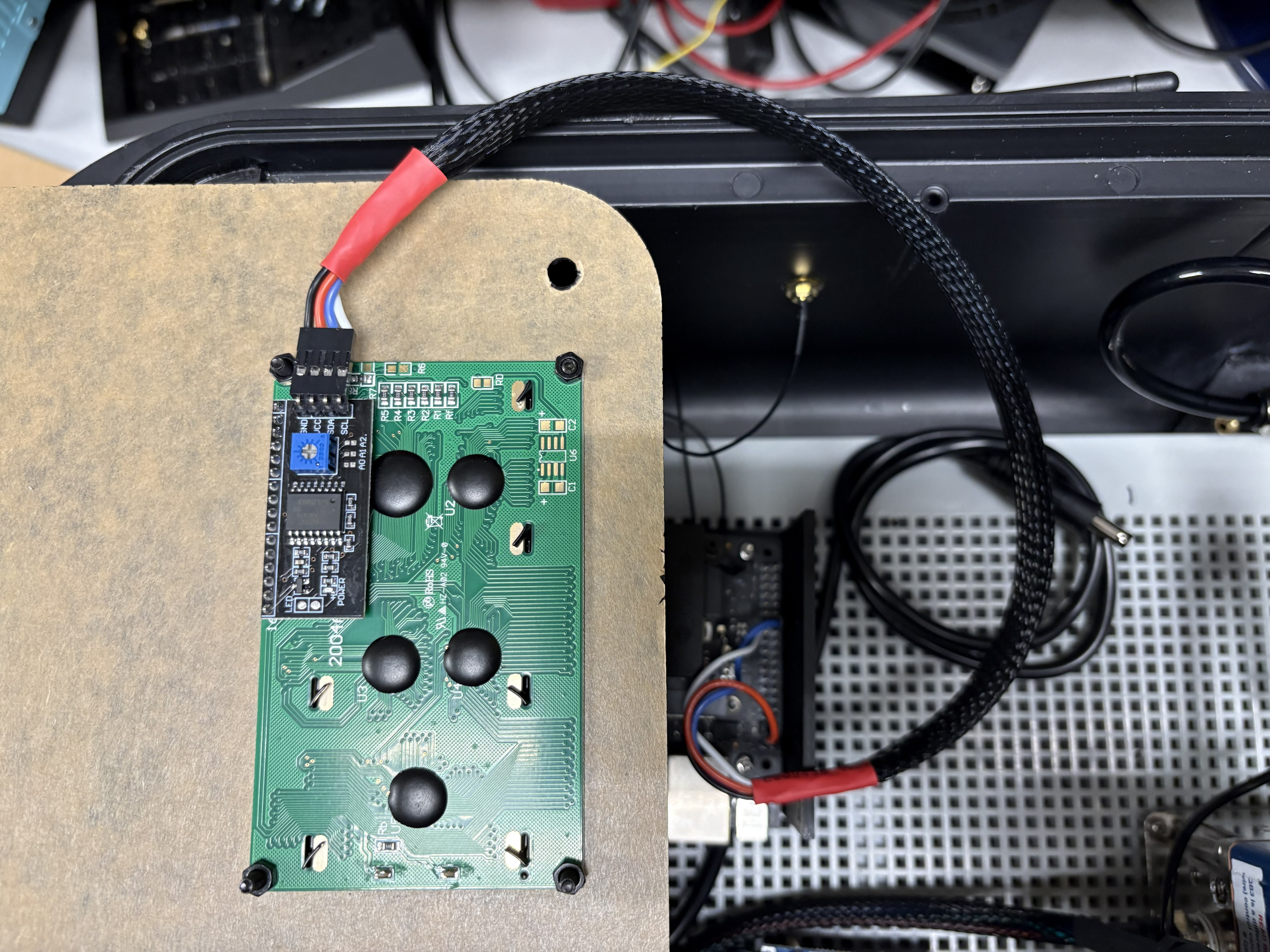
Connect the cable with Dupont connectors coming from the Jetson to the LCD screen.
-
Connect the USB 3.0, A-to-A, Male-to-Male cables (2) to the panel ports. Connect the Ethernet Extension Cable 1ft Female-to-Male as well.
-
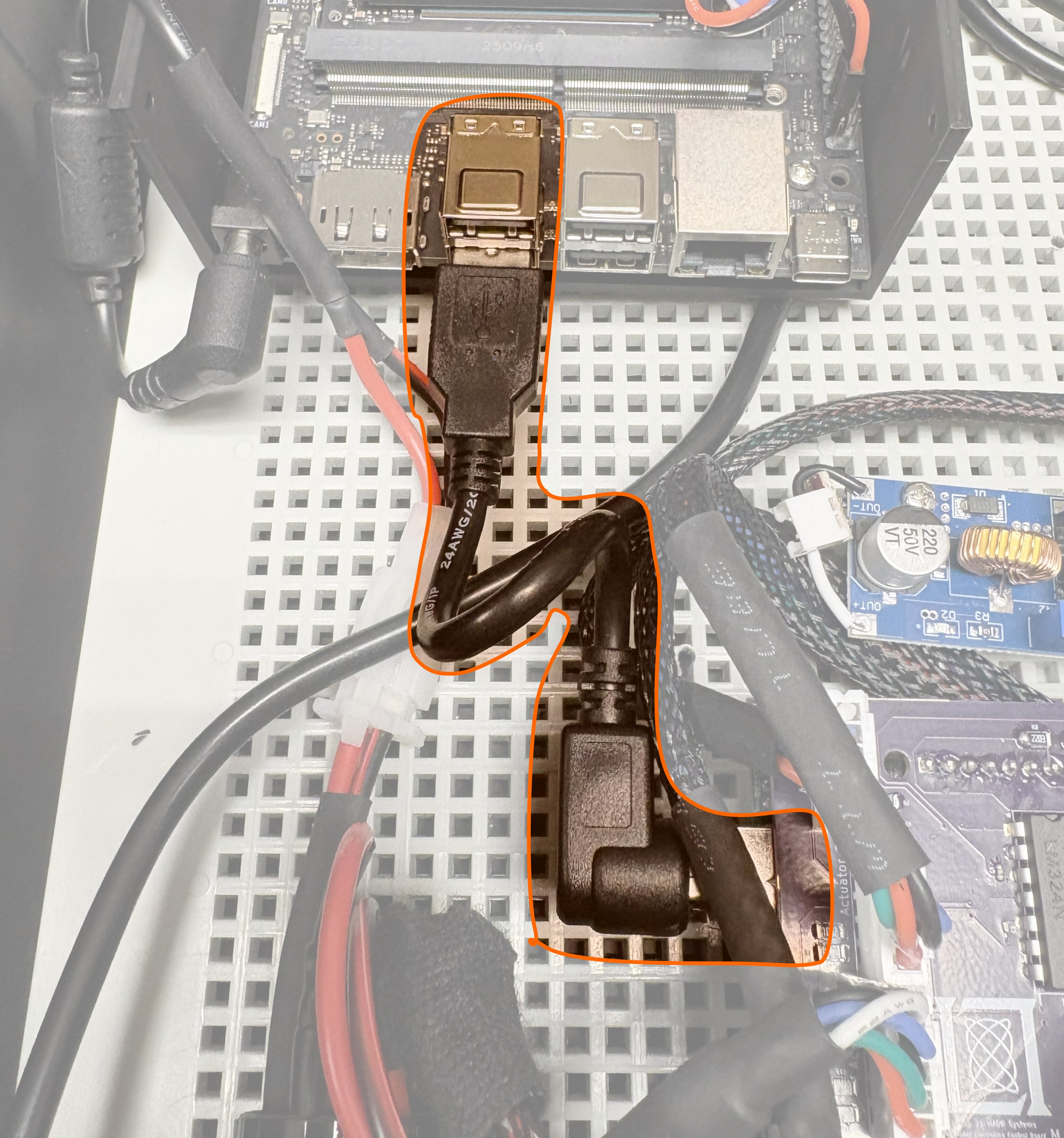
Connect the Right Angle USB A to USB B male connector from the Arduino to the Jetson.
-
Connect the USB A and ethernet cables to the Jetson. Connect the DP-to-HDMI cable as well.
-
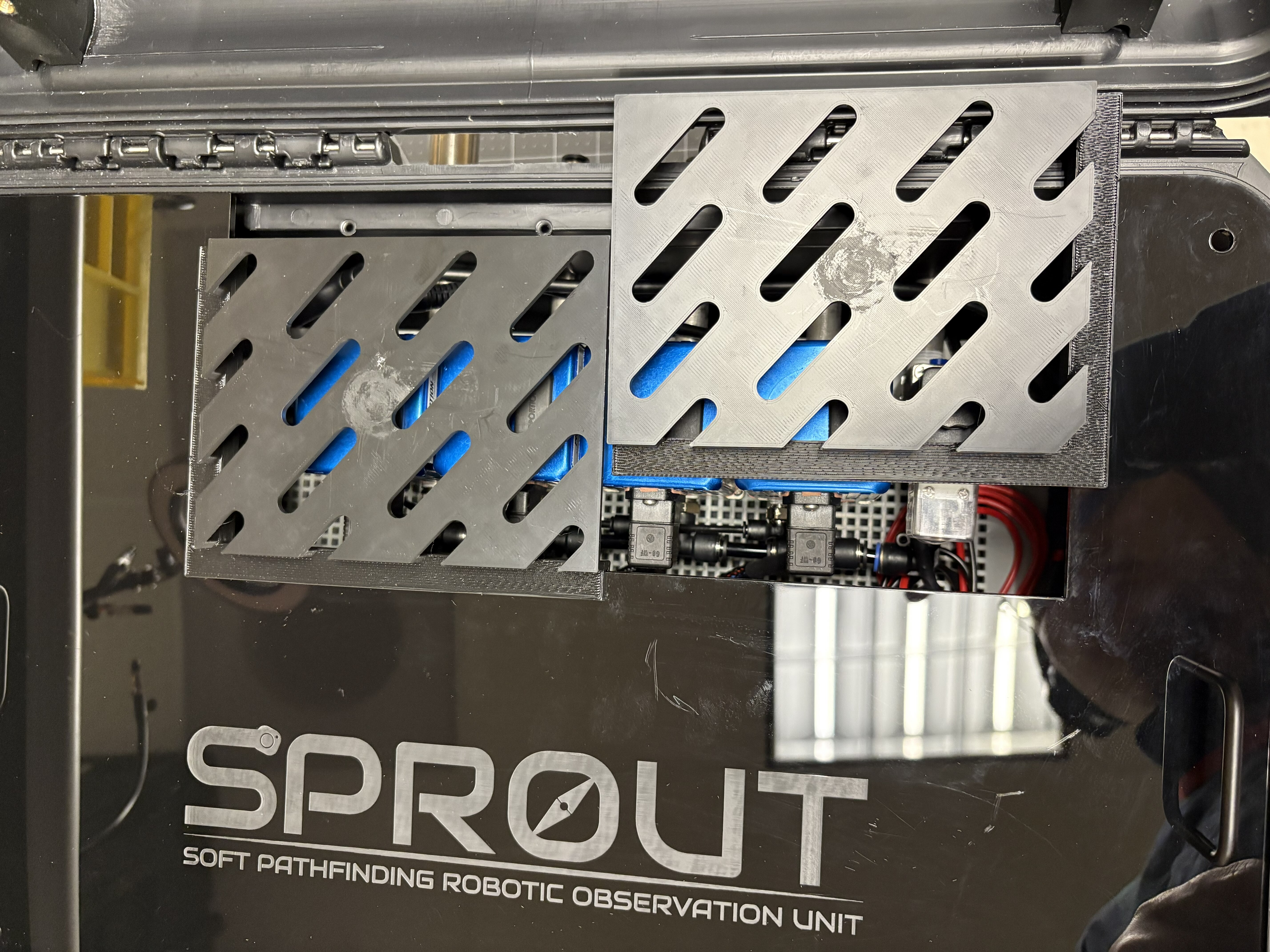
Rest the panel in position over the interface panel mounts. 3D-print the vents and slide them into the panel.
Step 7: Screen installation
Required components
| Item | Qty |
|---|---|
| 15” LCD Display | 1 |
| M5 Plastic-Head Thumb Screws | 8 |
Procedure
-
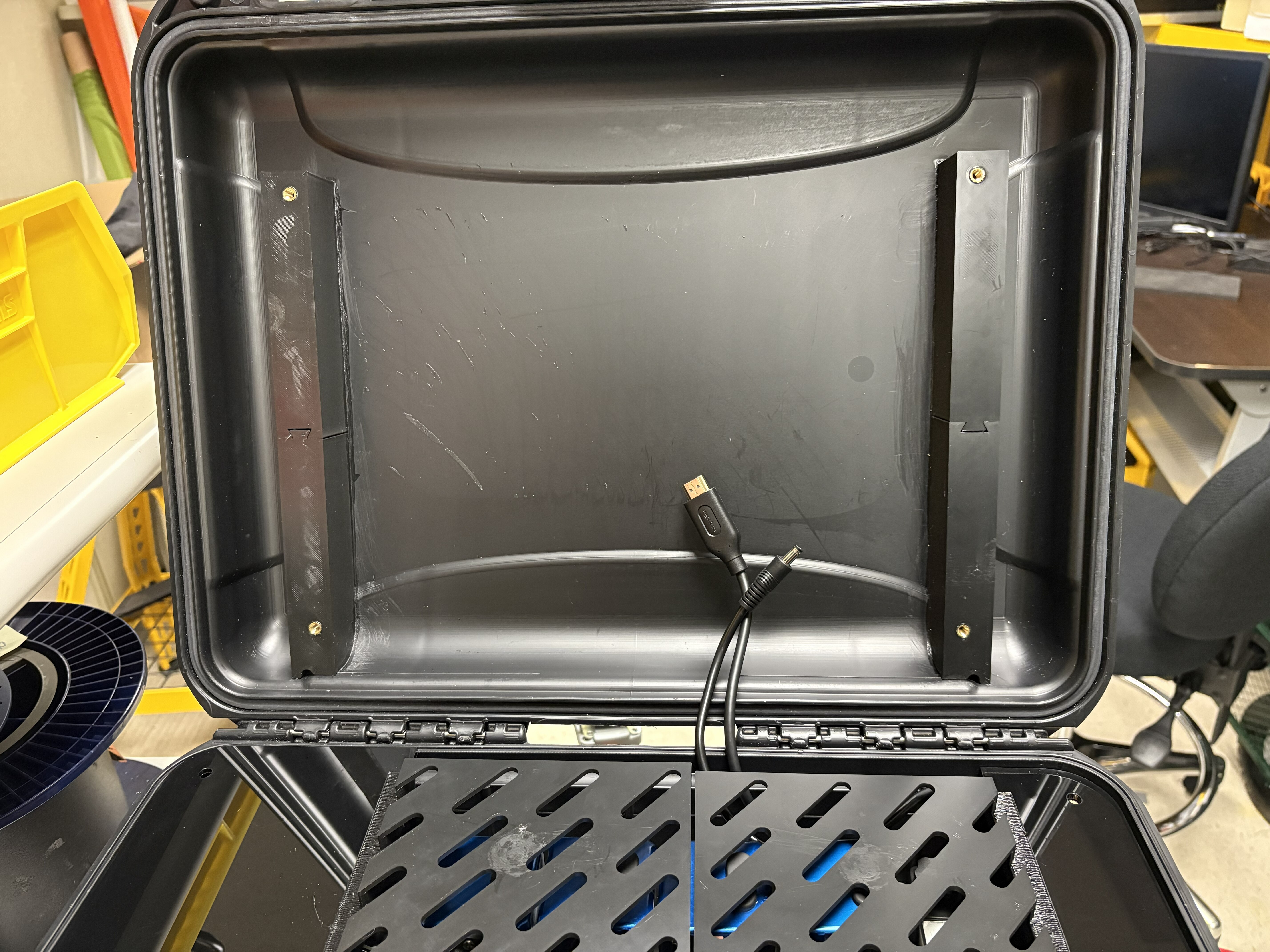
Pass the HDMI cable and the power cable (from Step 2.10) around the mounting plate and behind the vents, as shown below. Connect these to the screen.
-
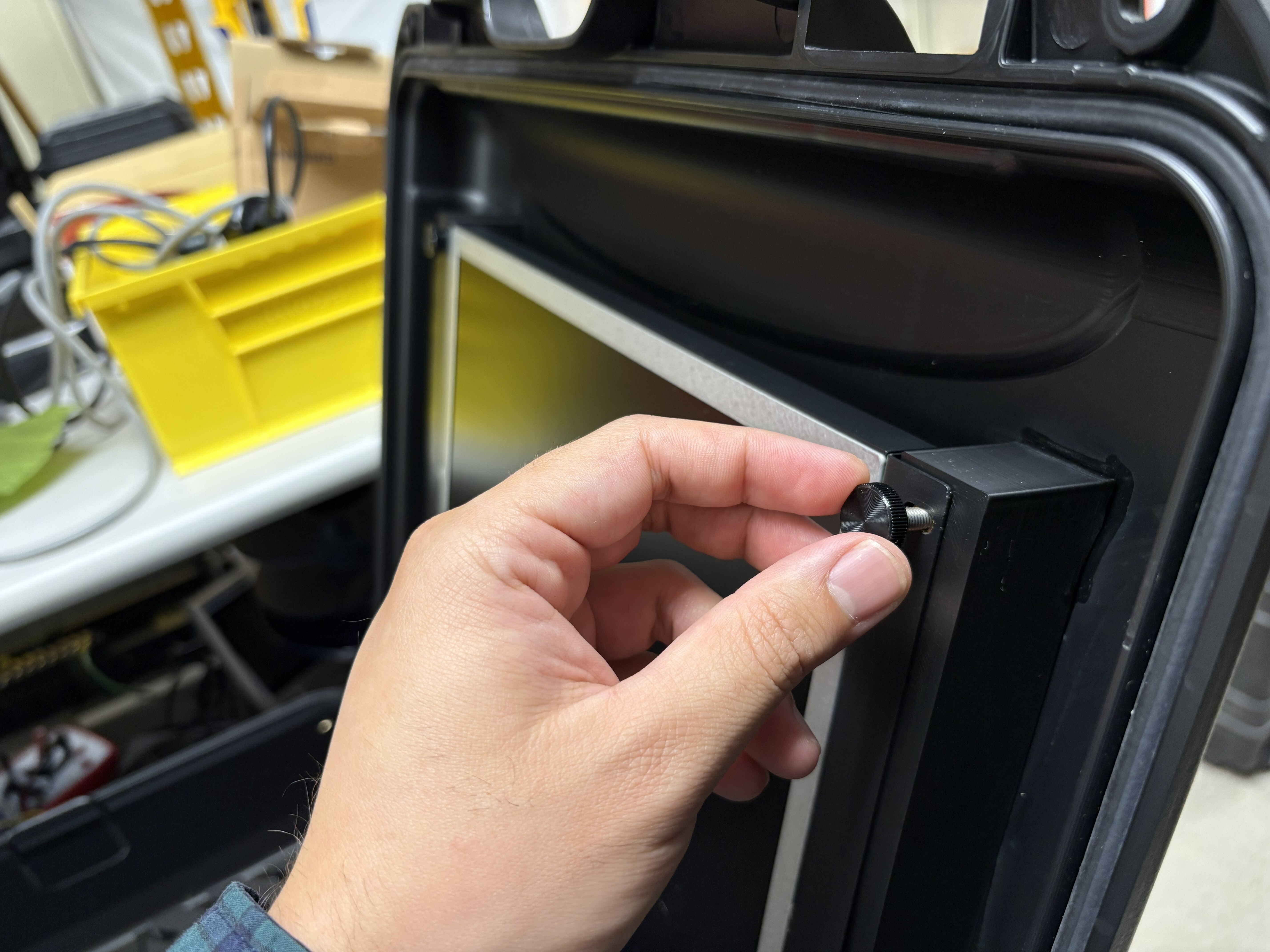
Using the thumb screws, mount the screen to the 3D-printed brackets.
-
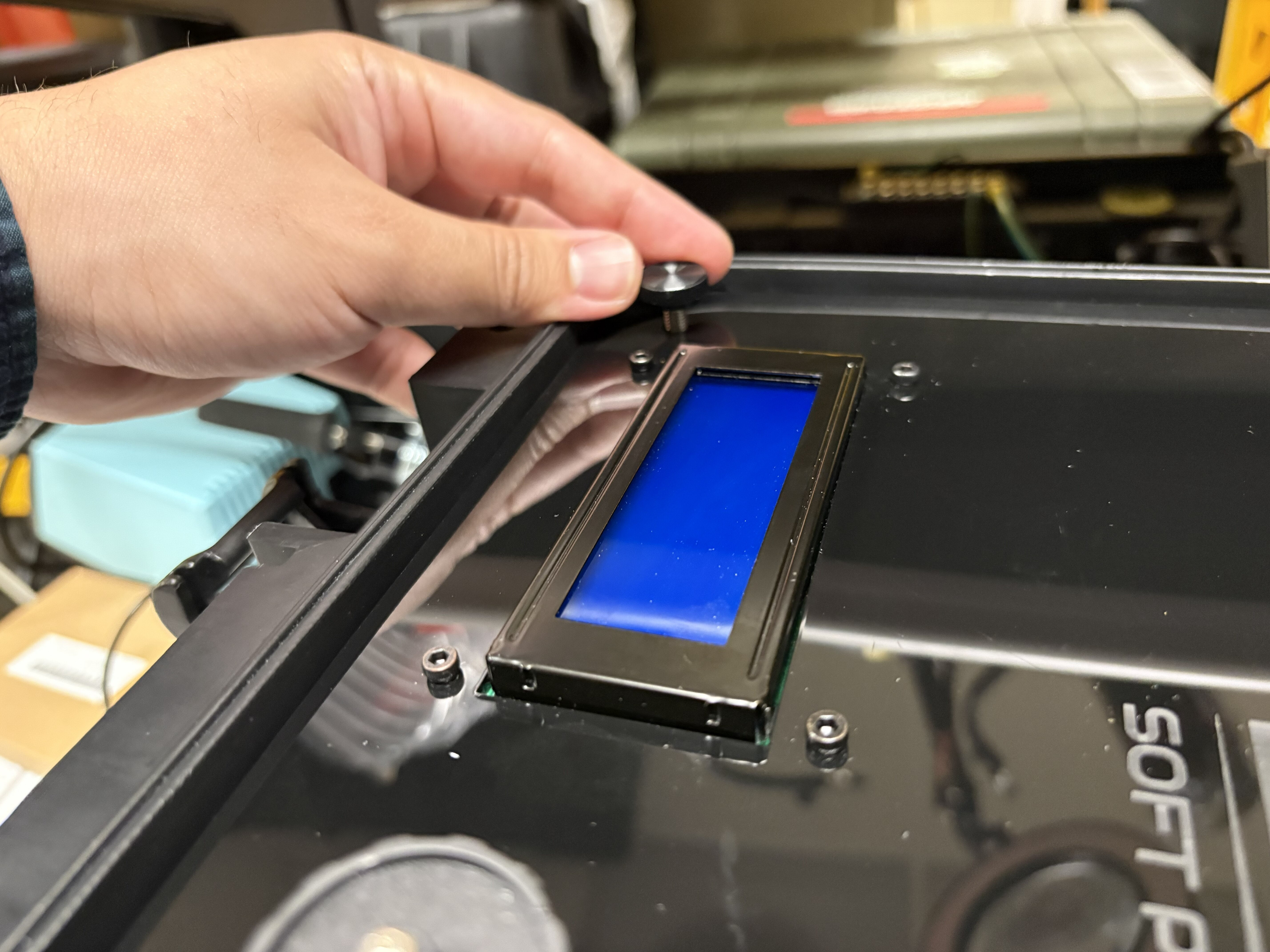
After this, the peripherals panel can be fastened to the mounting brackets using thumb screws.
Step 8: Assembly with robot base
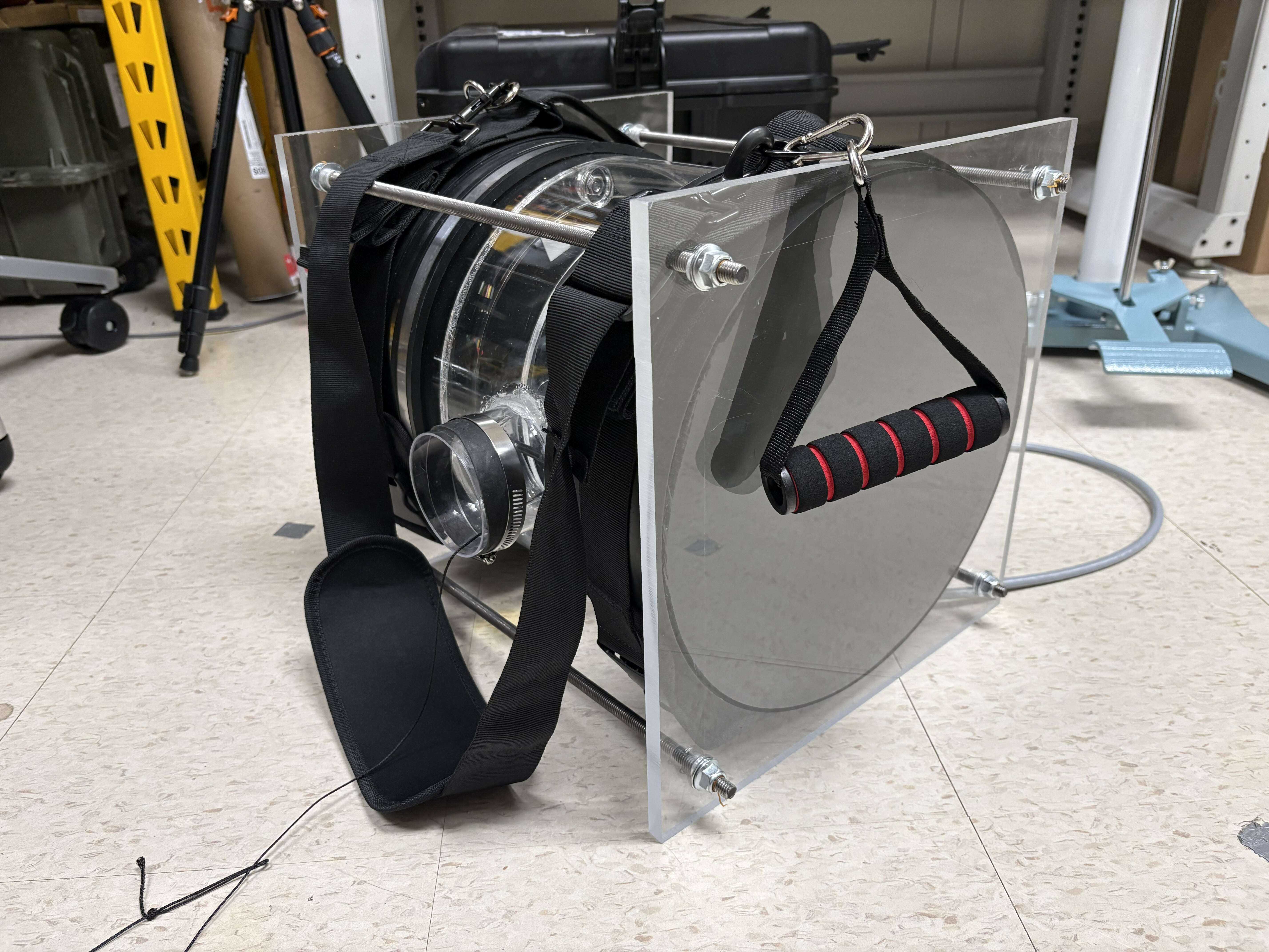
The base shown in these steps was built using the vinerobots.org base construction steps. A few modifications have been made, but the overall shape and functionality are identical to the one on the Vine Robots website.
List of changes:
- The reel has been modified to include heat-set inserts, so the acrylic plates can be fastened into the 3D-printed reel core instead of hot-glued.
- The reel core has been modified to feature a shallow concave groove designed to passively guide the tendon toward the center of the spool during winding.
- As a safety precaution, 1/2” thick acrylic plates are secured with threaded rods to the sides of the base. This ensures the rubber ends do not come off due to over-pressurization or faulty hose clamp installation.
- We added a shoulder strap and carrying handles to facilitate base carrying.
Procedure
To finish the assembly, we will mount the compute box in the robot base.
-
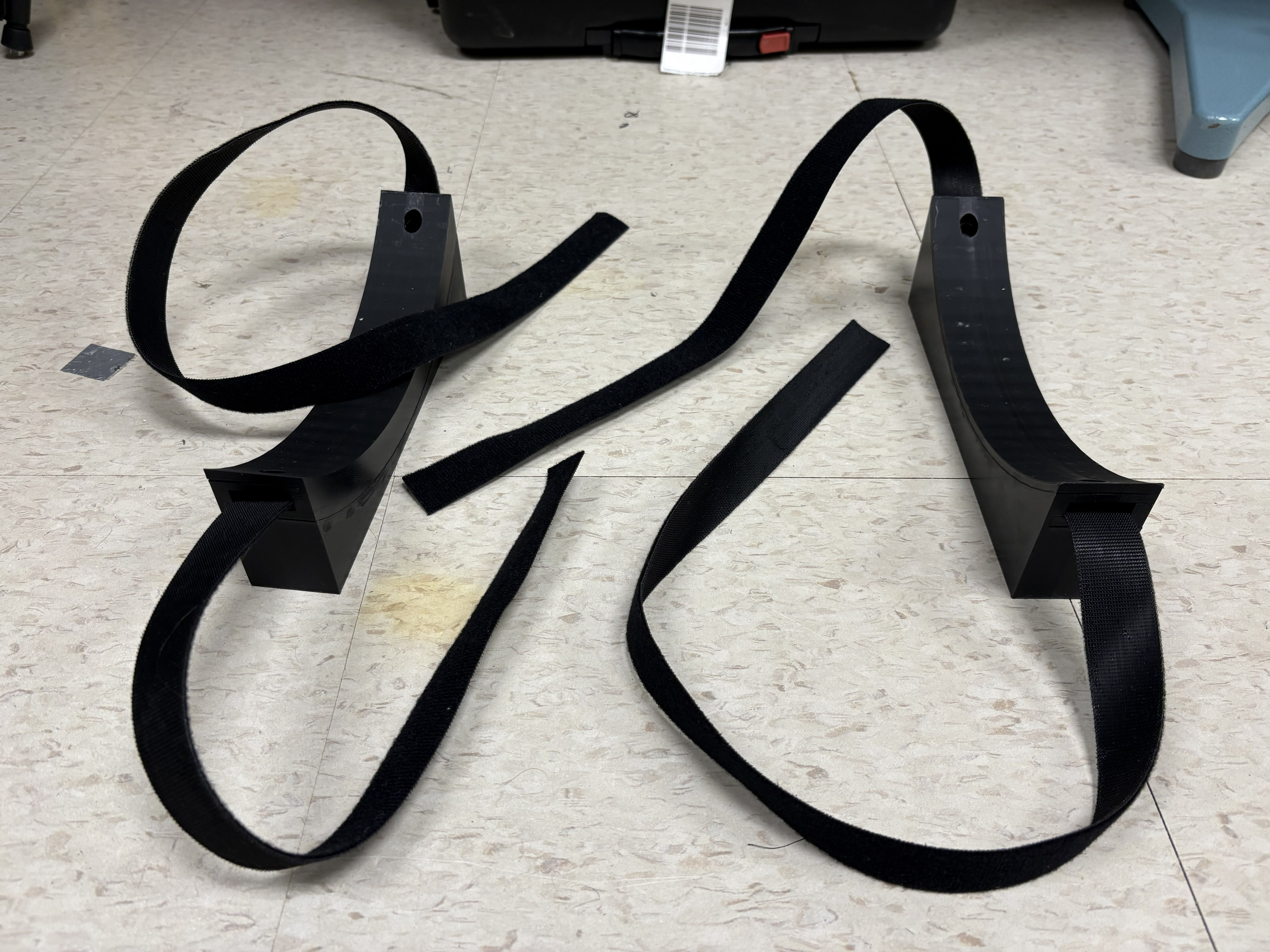
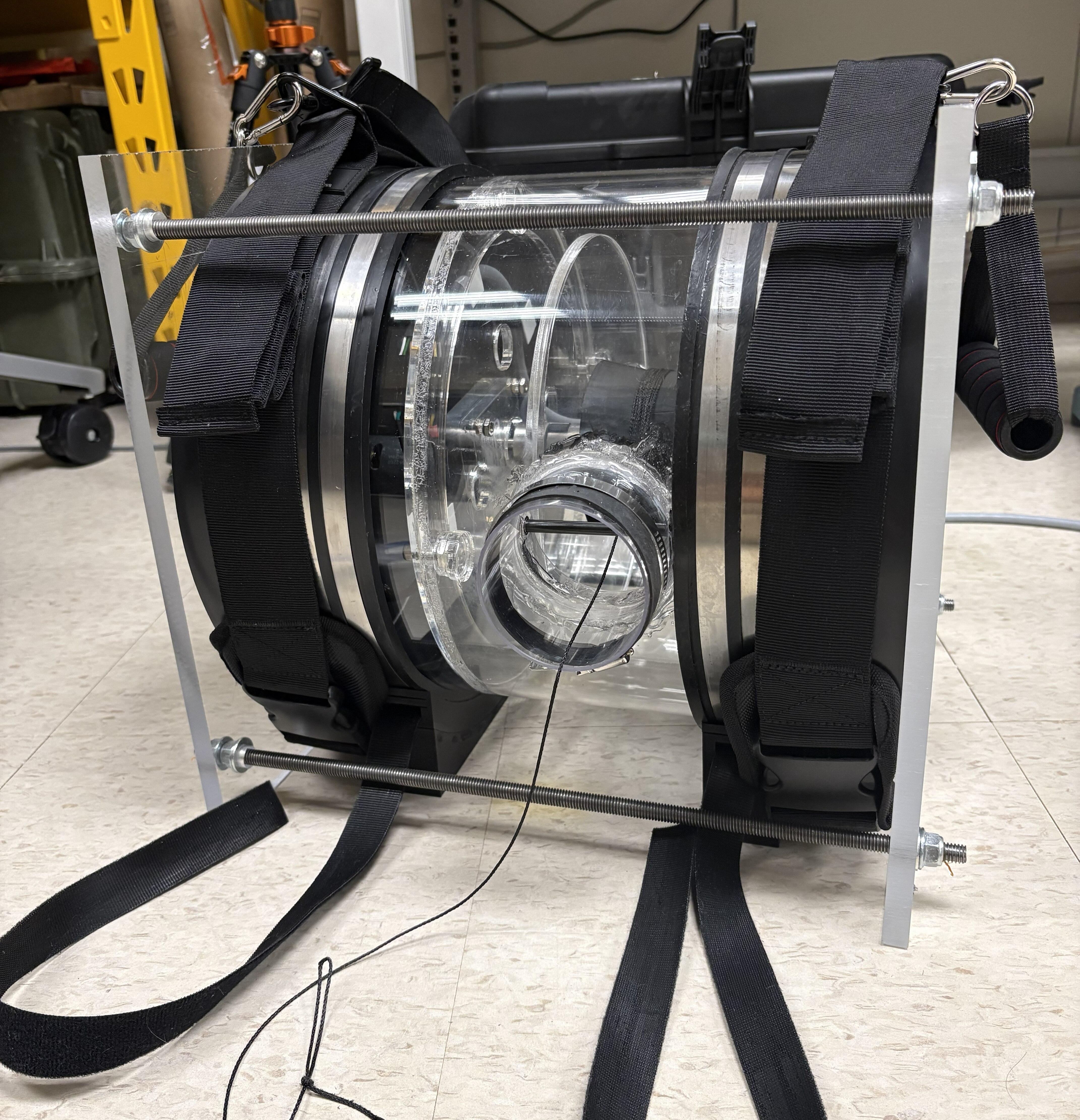
Print a second set of the curved foot assembly and place them on the floor, and pass velcro or ratchet straps on the foot assembly orifices.
-
Sit the cylindrical robot body on top of these.
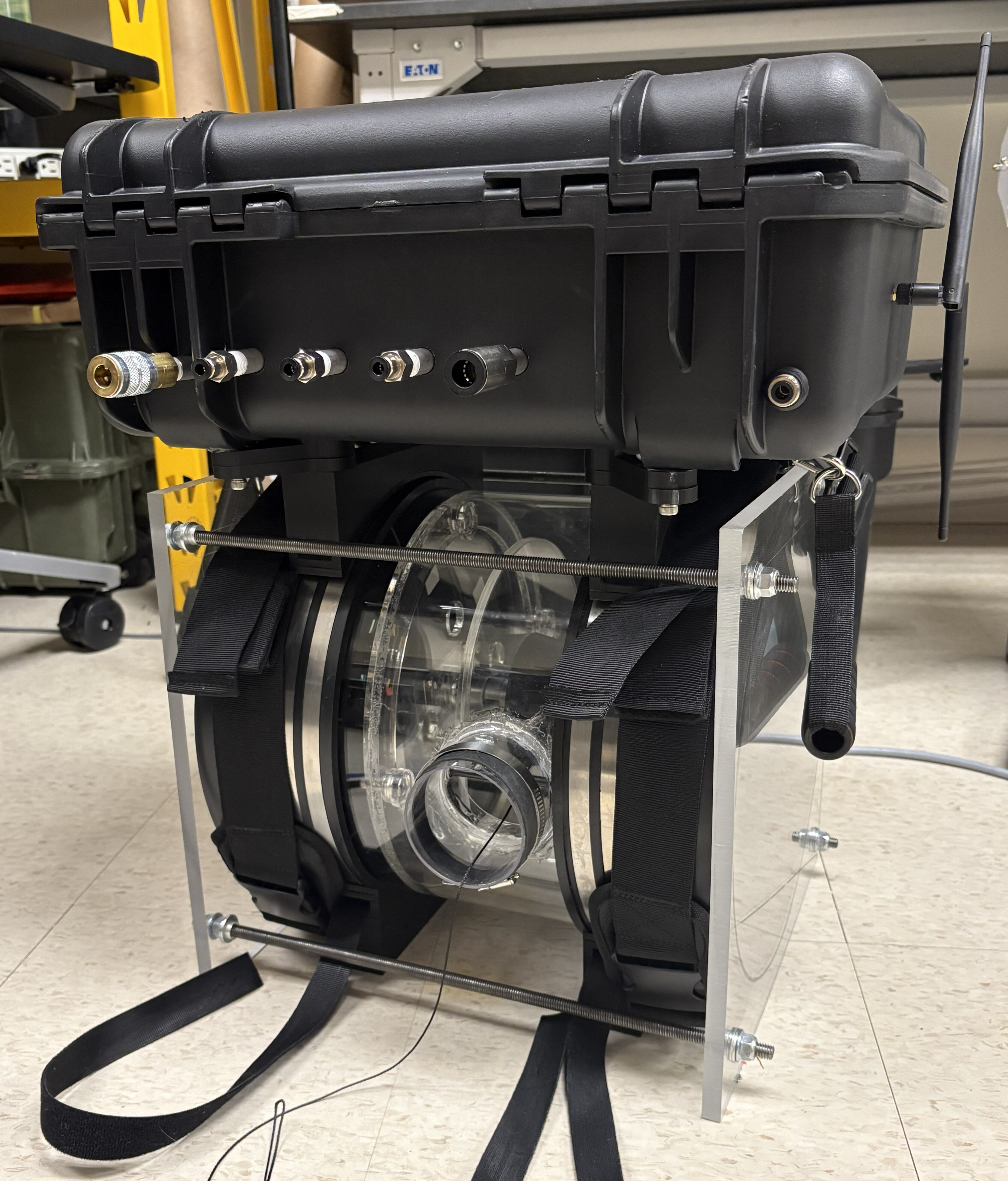
-
Then, place the compute box on top of the robot.
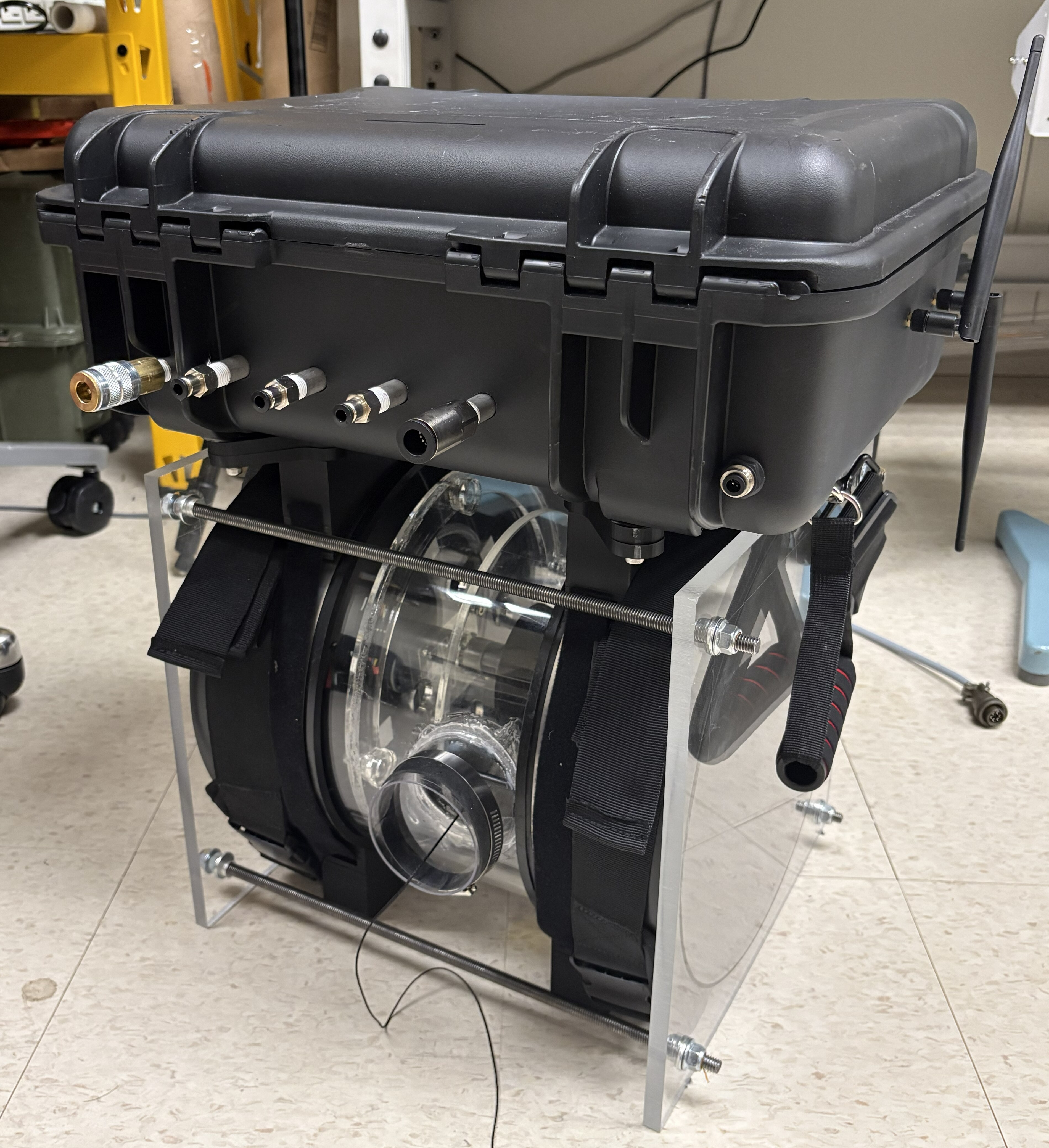
-
Tighten the straps to secure the compute box around the cylindrical robot body. Connect the compute box to the vine robot base using the 6-pin receptacle, then attach a battery.
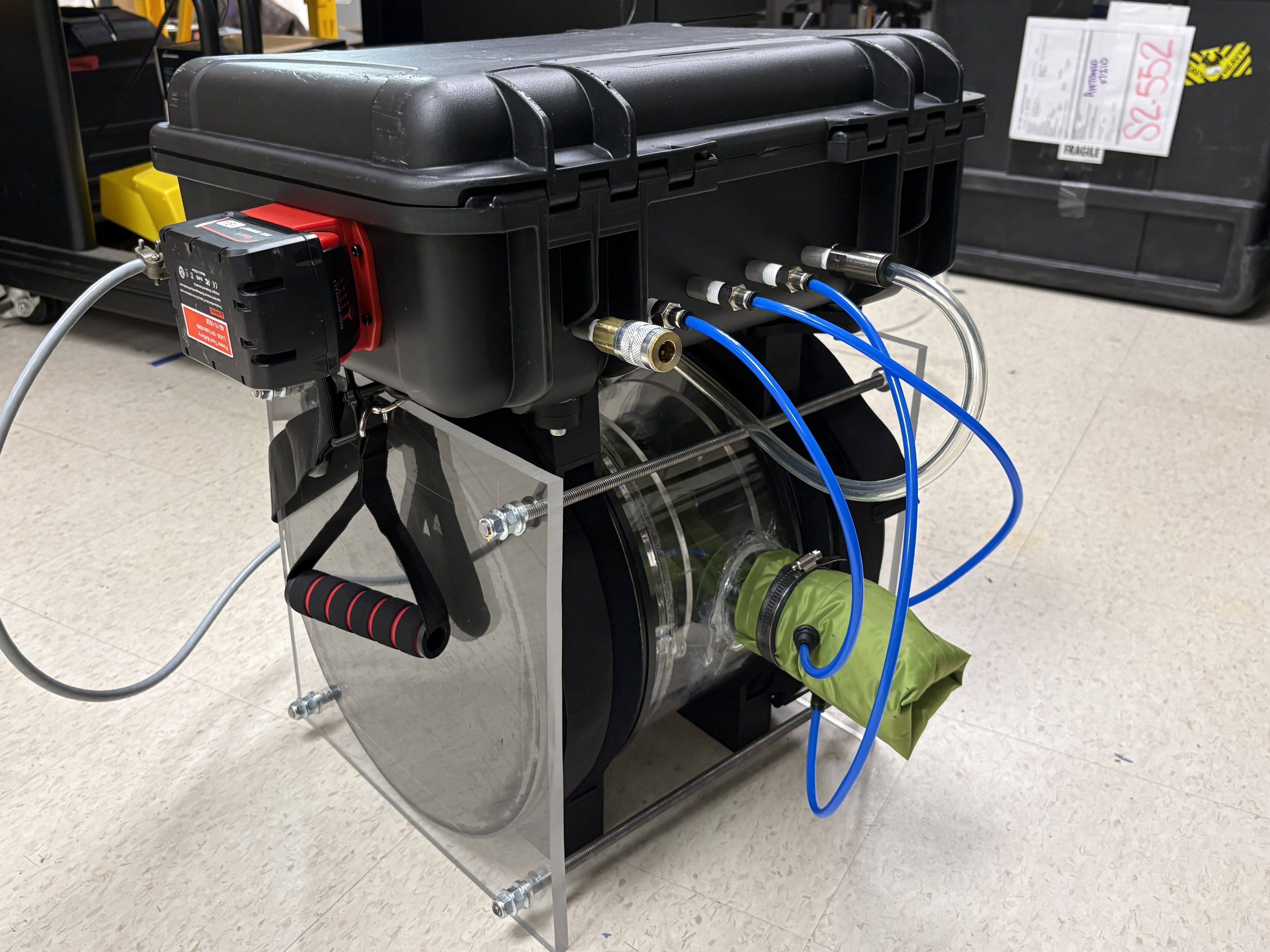
-
Finally, install a vine in the reel. Connect the robot base to the pneumatic outputs. The 1/2” push-to-connect provides pressure to the main connector of the robot base; the 3x 1/4” push-to-connect fittings provide pressure to the robot body pouch motor lines. The quick-disconnect connector is the main pressurized air inlet, to be connected to a compressor or pressurized air tank.
-
Attach a joystick to the compute box, and the system assembly is complete!
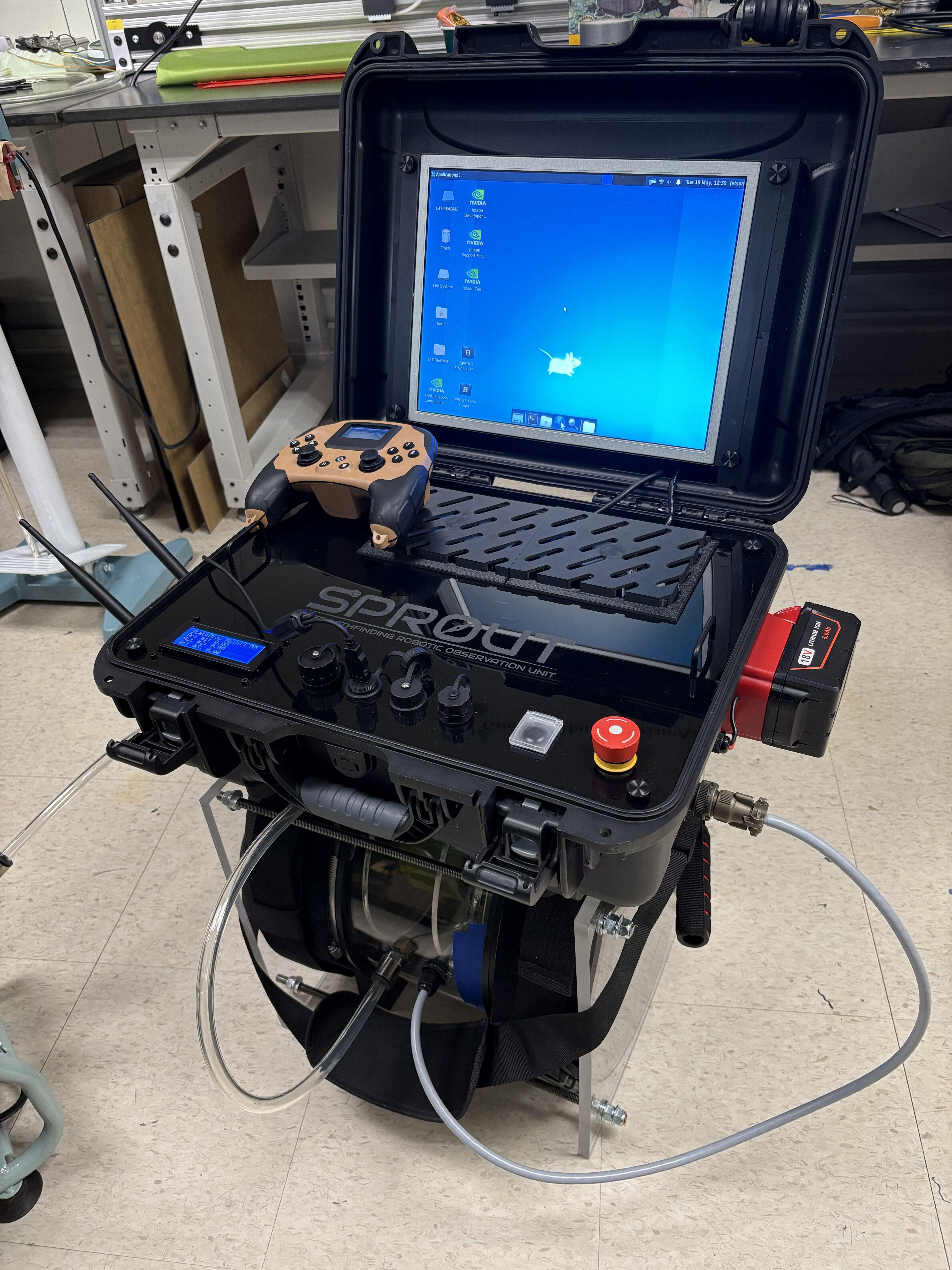
See Vine Construction for building the vine itself.
Step 9: Final inspection
Verify:
- all hardware is secured
- all connectors are fully seated
- all wiring is strain relieved
- no loose hardware remains
- the enclosure lid closes without interference
Next steps
Proceed to Software Setup to flash and configure the Jetson, then run through validation testing before field deployment.