Wiring
Table of contents
Disconnect all power sources before making or changing any connections described below.
Section 1: Mounting plate electrical connections
-
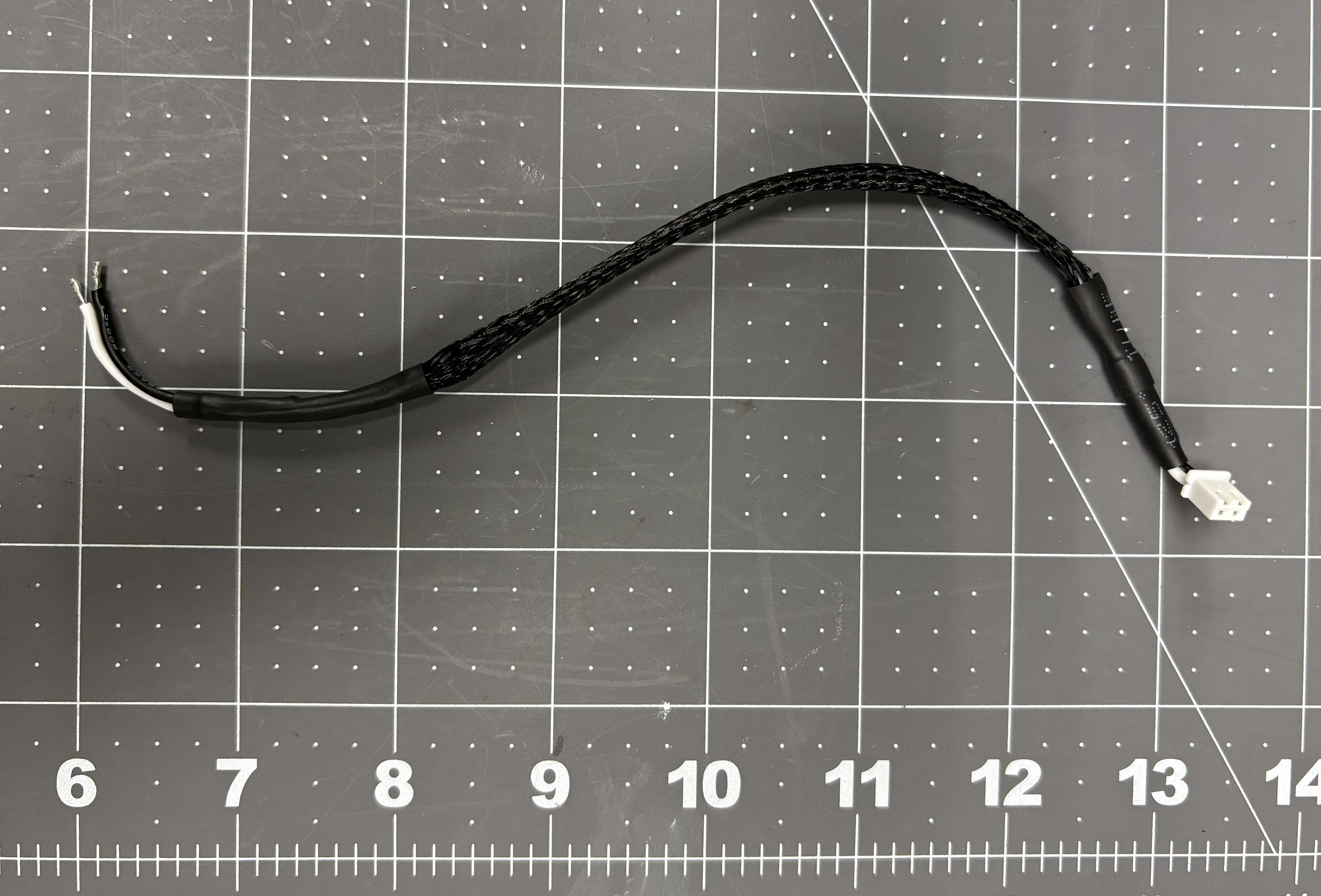
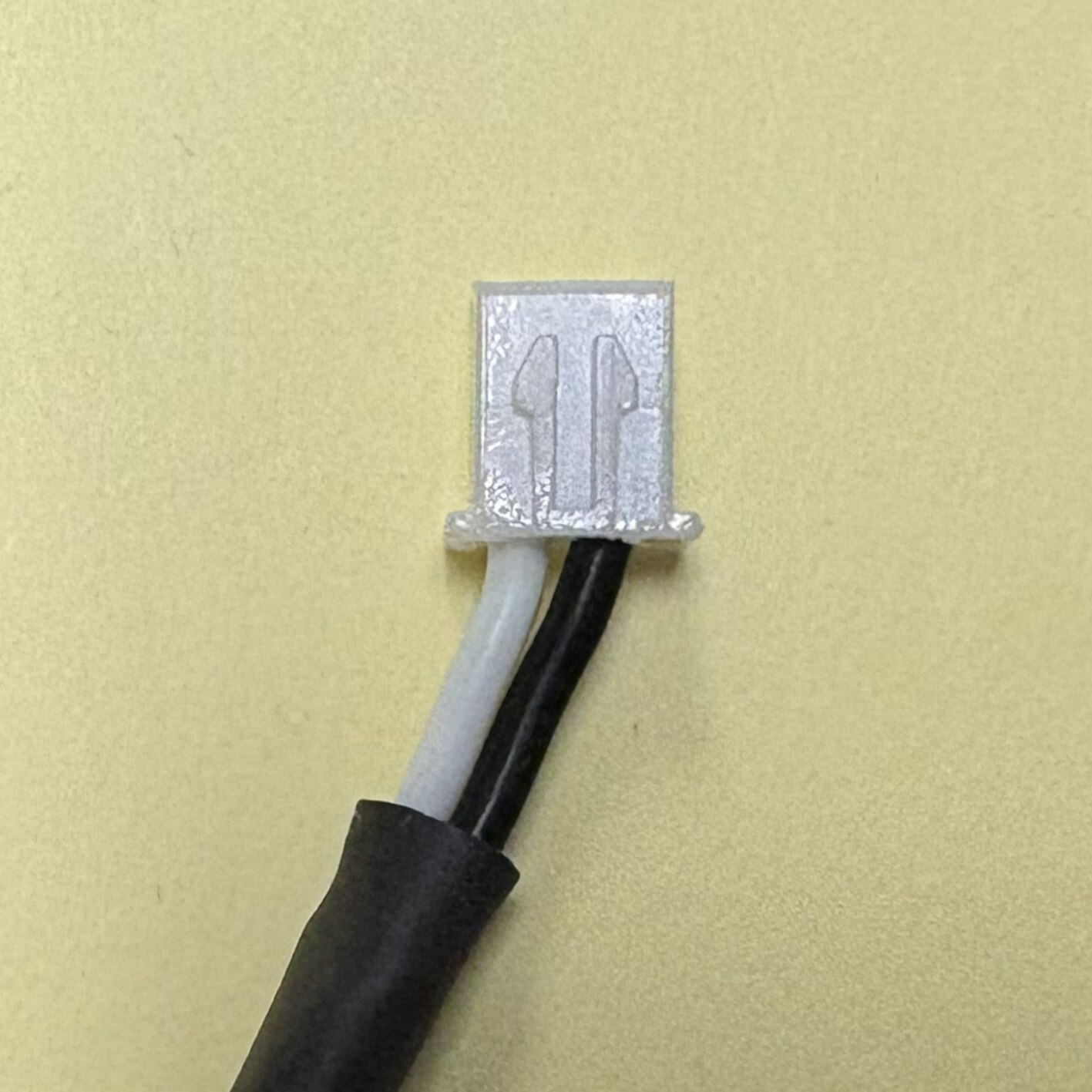
Cut 2-22 AWG stranded wire segments (about 8” long each). On one end, install a 2-pin JST-HX male connector. Leave the other end bare. Cover wire with sleeve mesh and heat-shrink tubing.
-
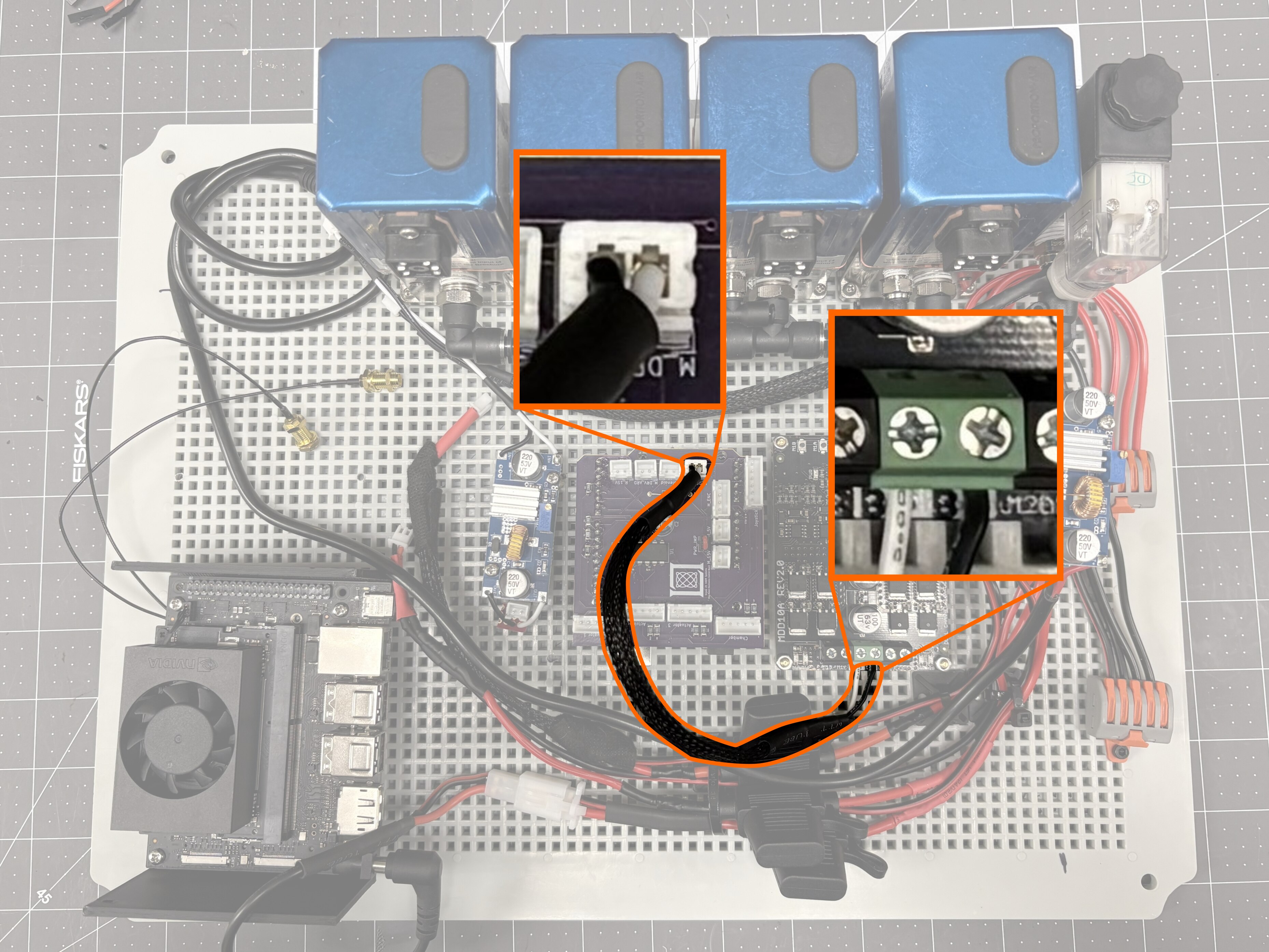
Connect the JST-HX male port to M_DRV_PWR in the arduino shield. Connect the bare white wire to B+ in motor driver board, and bare black wire to B-.
-
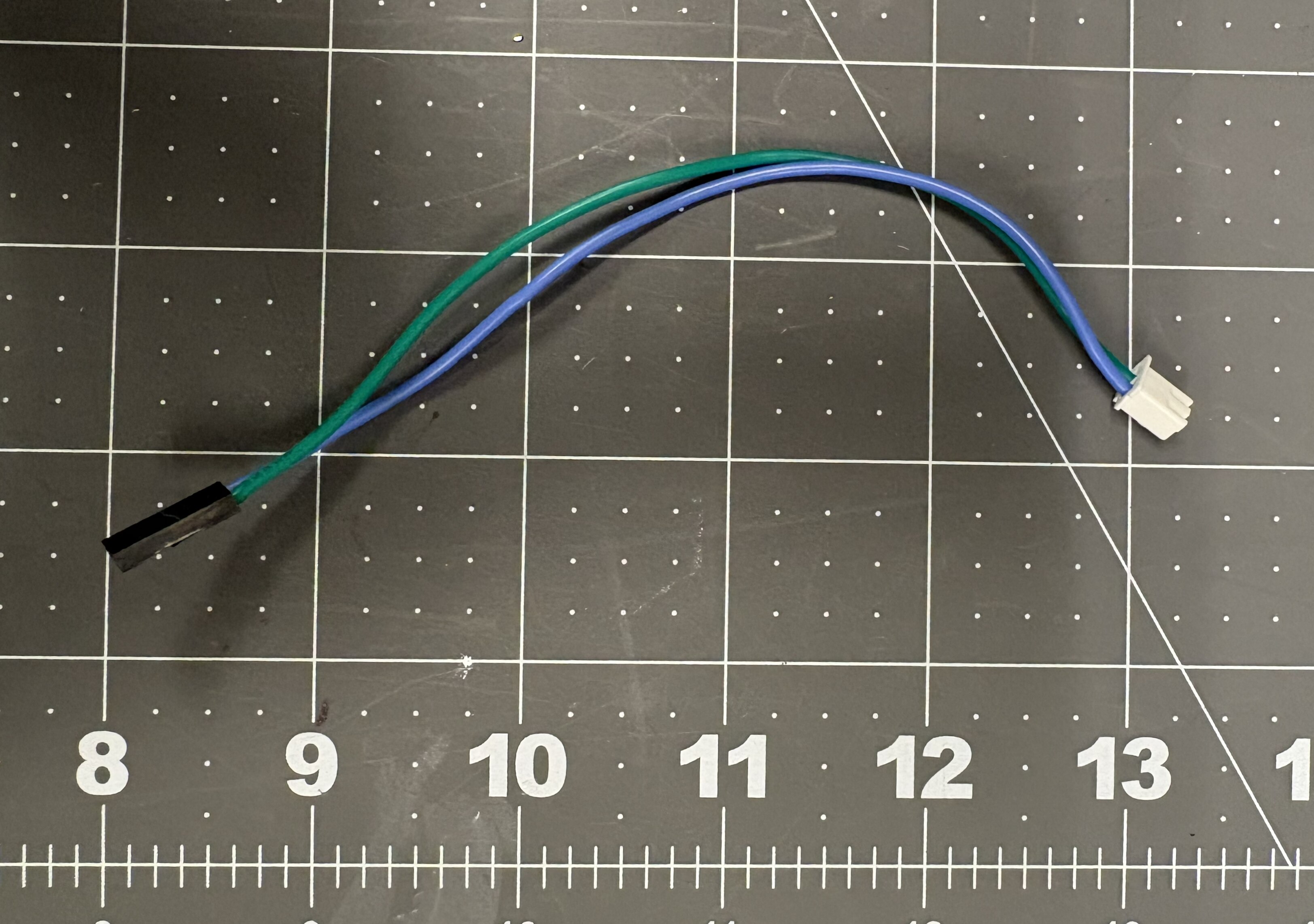
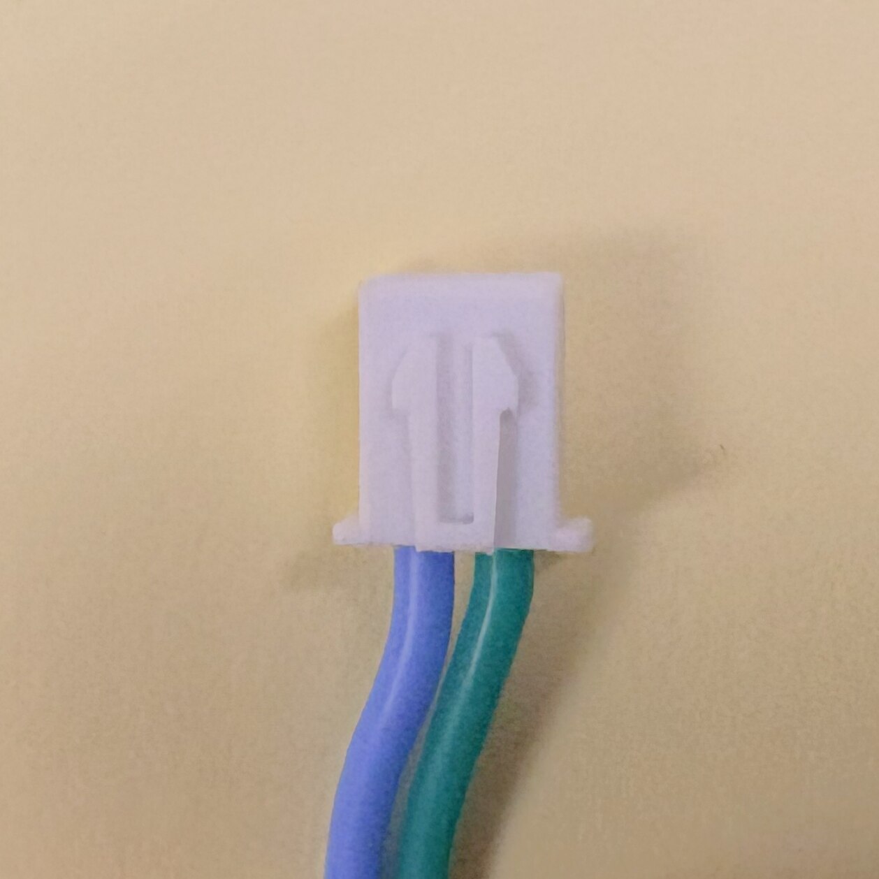
Cut 2-22 AWG stranded wire segments (about 6” long each). On one end, install a 2-pin JST-HX male connector. On the other end, install a 2-pin female Dupont connector.
-
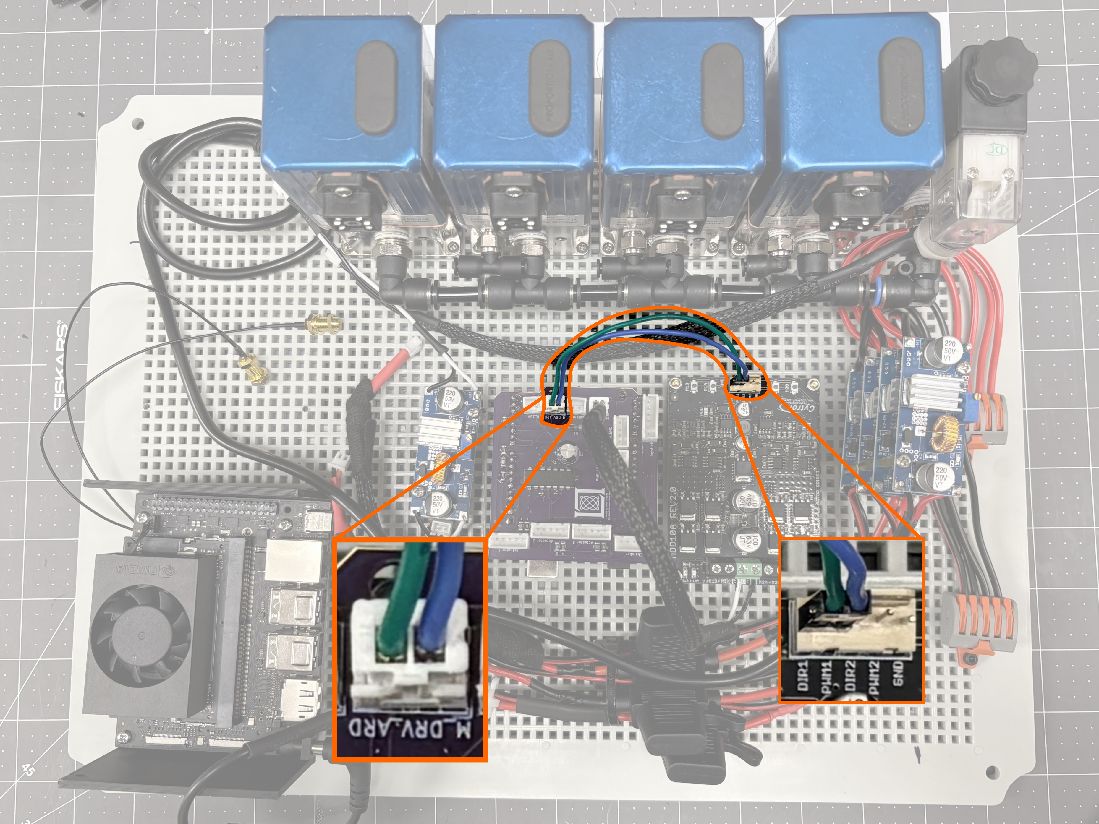
Connect the JST-HX male port to M_DRV_ARD in the arduino shield. Connect the Dupont wires to the motor driver (green wire to DIR1, blue wire to PWM1).
-
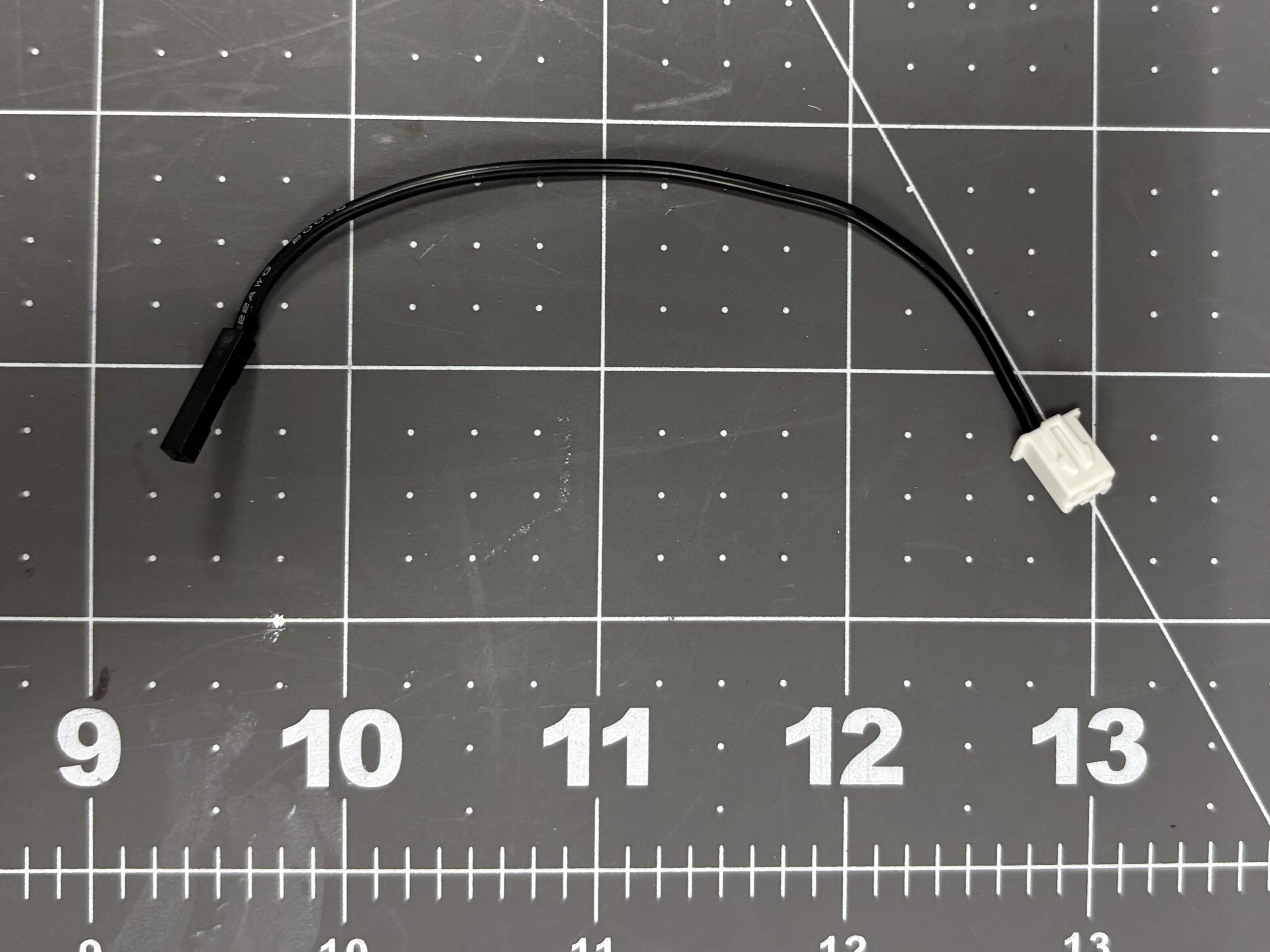
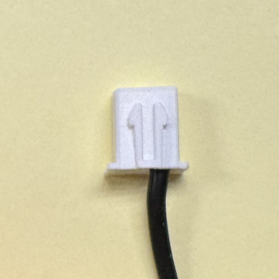
Cut 1-22 AWG stranded wire segment (about 5”). On one end, install a 2-pin JST-HX male connector. On the other end, install a 1-pin female Dupont connector.
-
Connect the JST-HX male port to M_5V in the arduino shield. Connect the Dupont wire to the motor driver (GND).
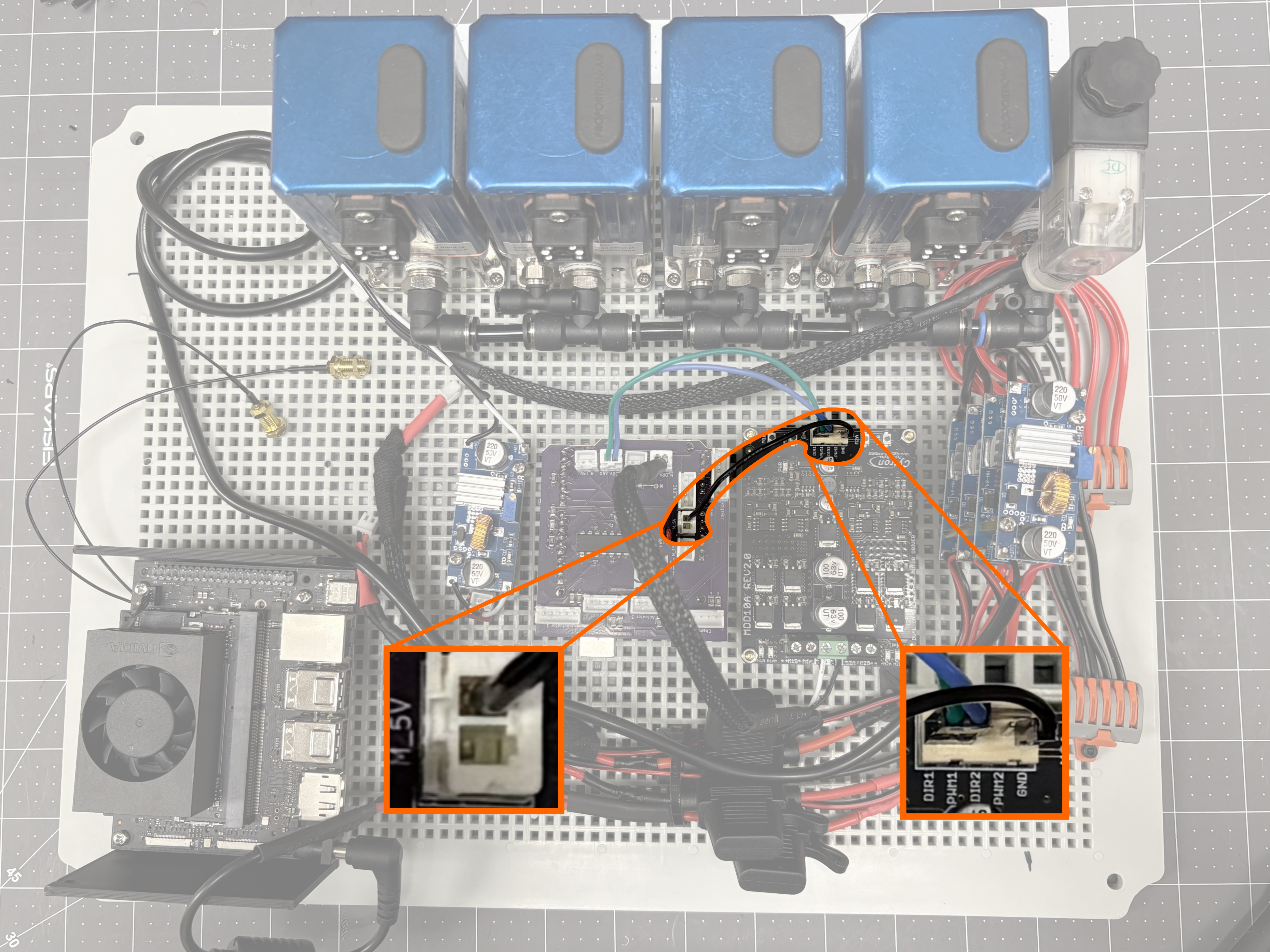
-
Connect the JST-HX male port from the buck converter INPUT to Solenoid in the arduino shield.
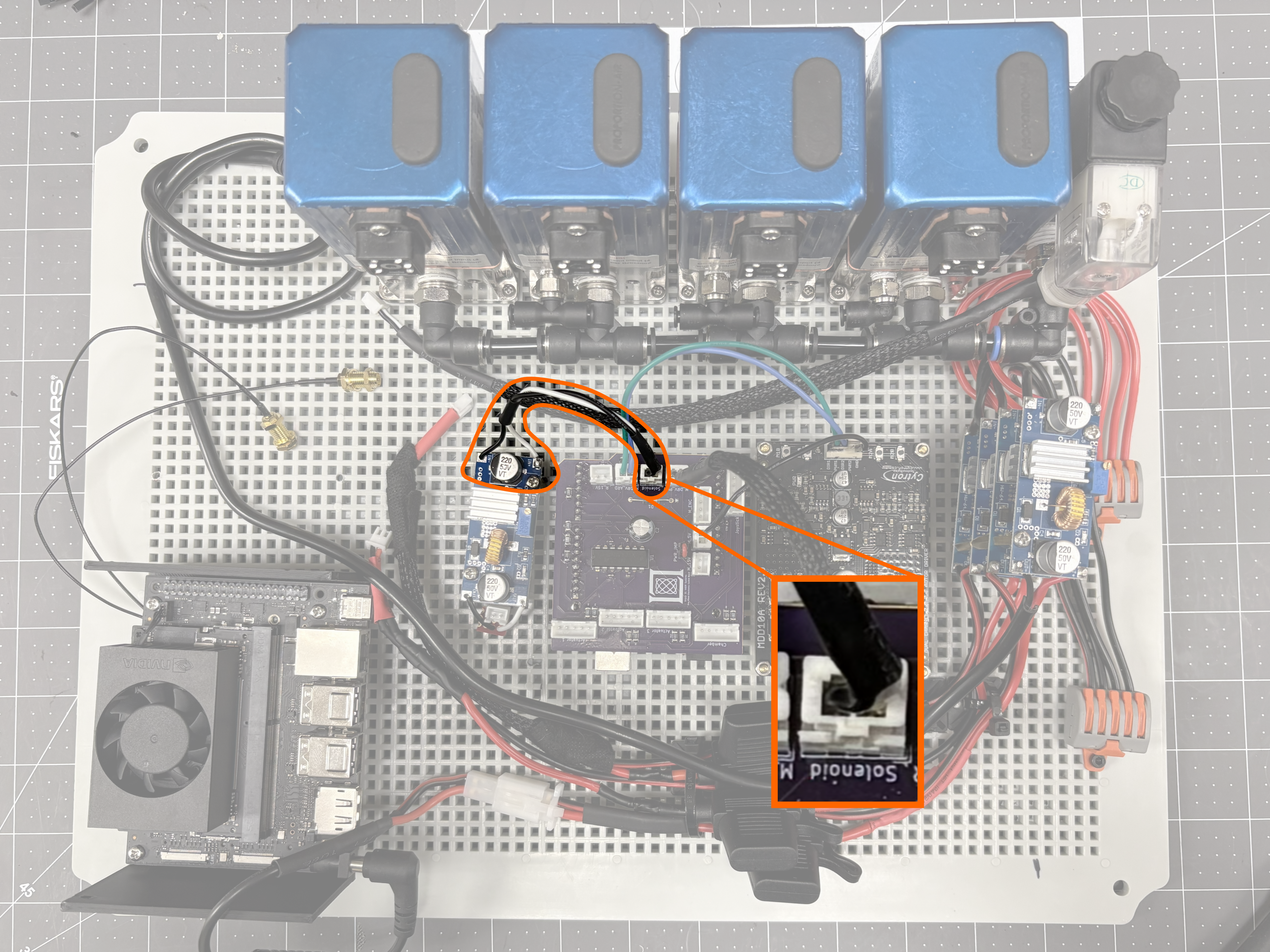
-
Connect the solenoid wiring to the buck converter OUTPUT.
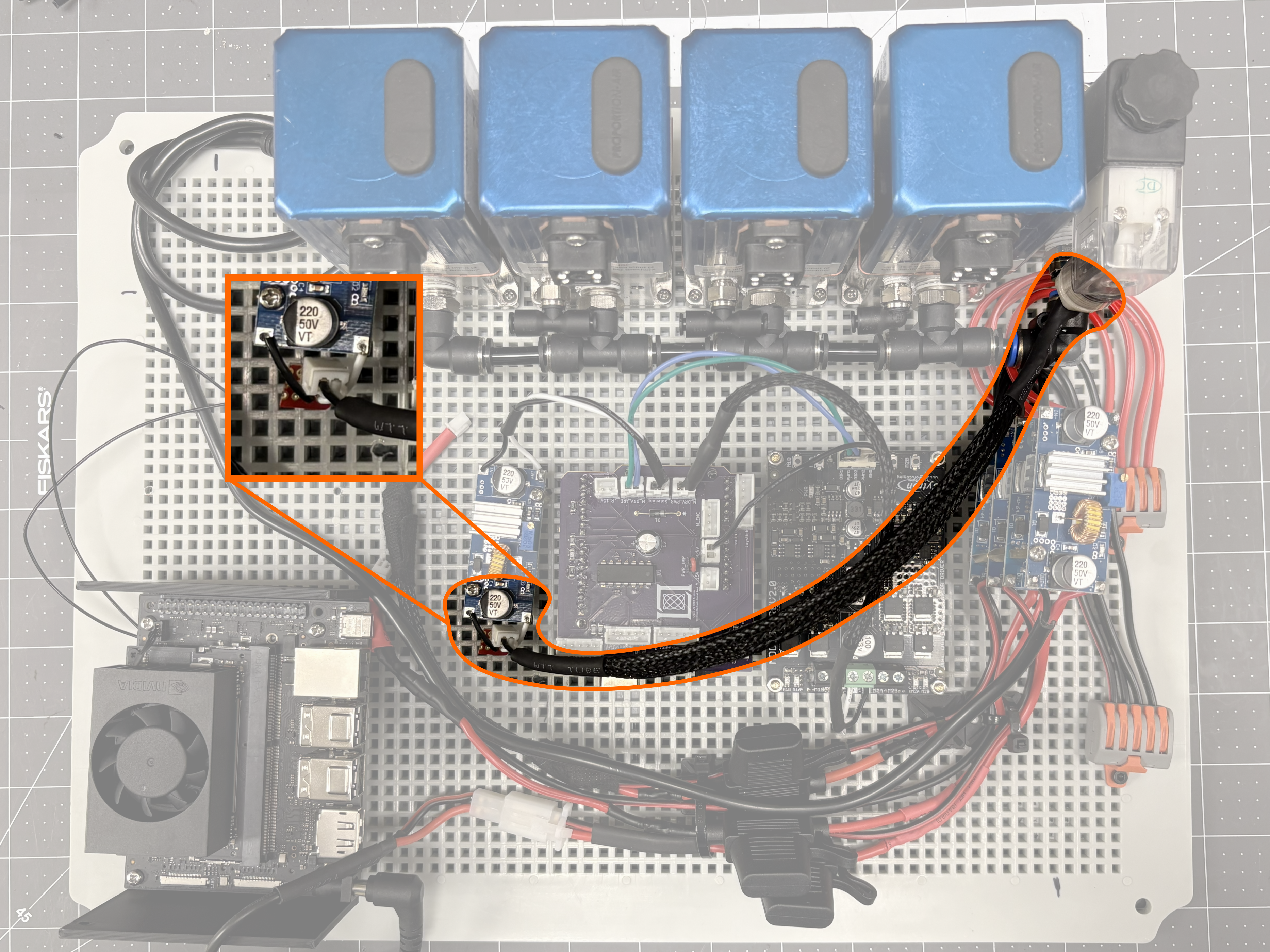
-
Connect one of the JST-HX terminated power cables from the 15V buck converters to M_15V in the arduino shield.
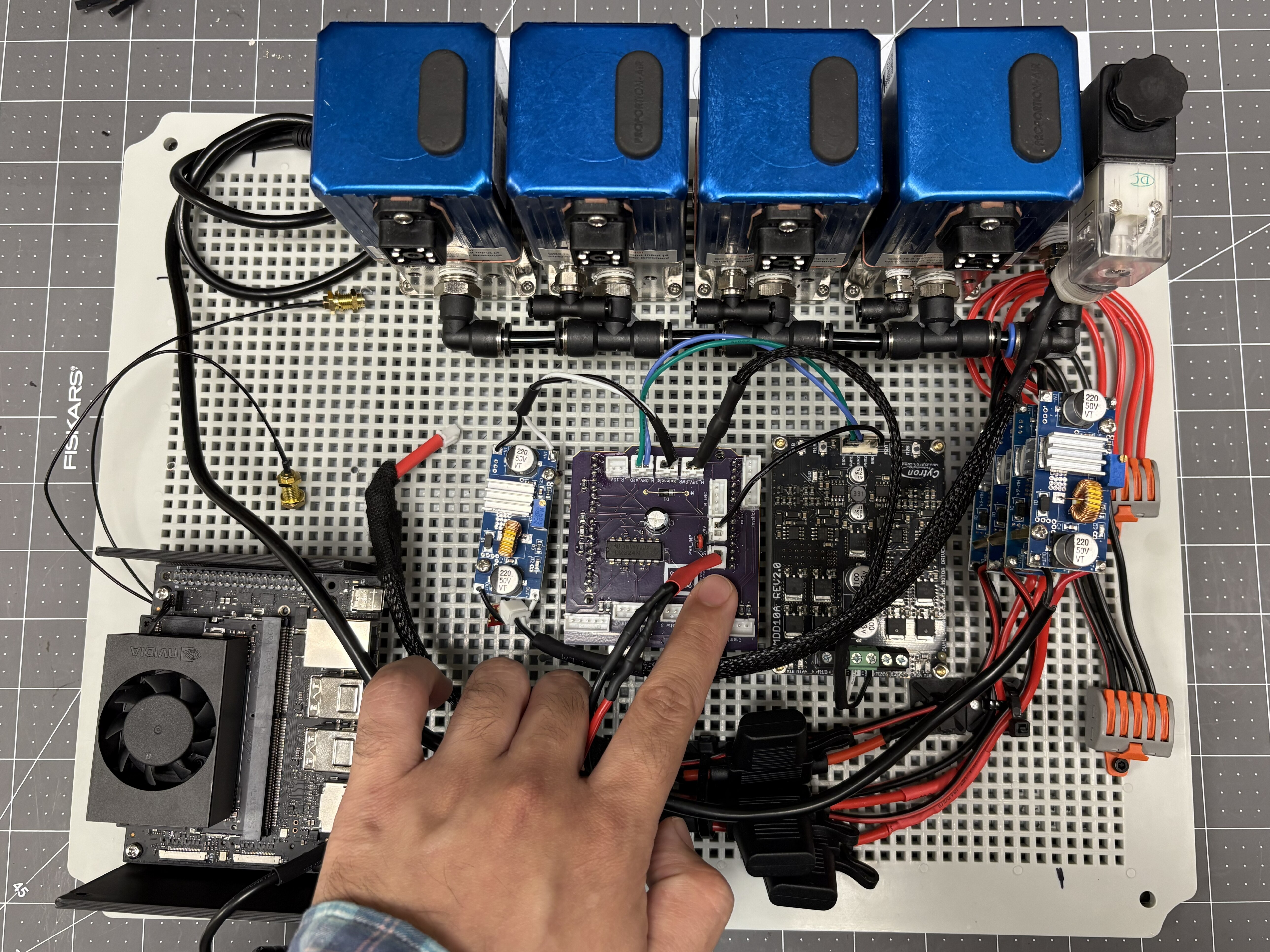
-
Connect the other 15V JST-HX terminated buck converter to R_15V in the arduino shield.
-
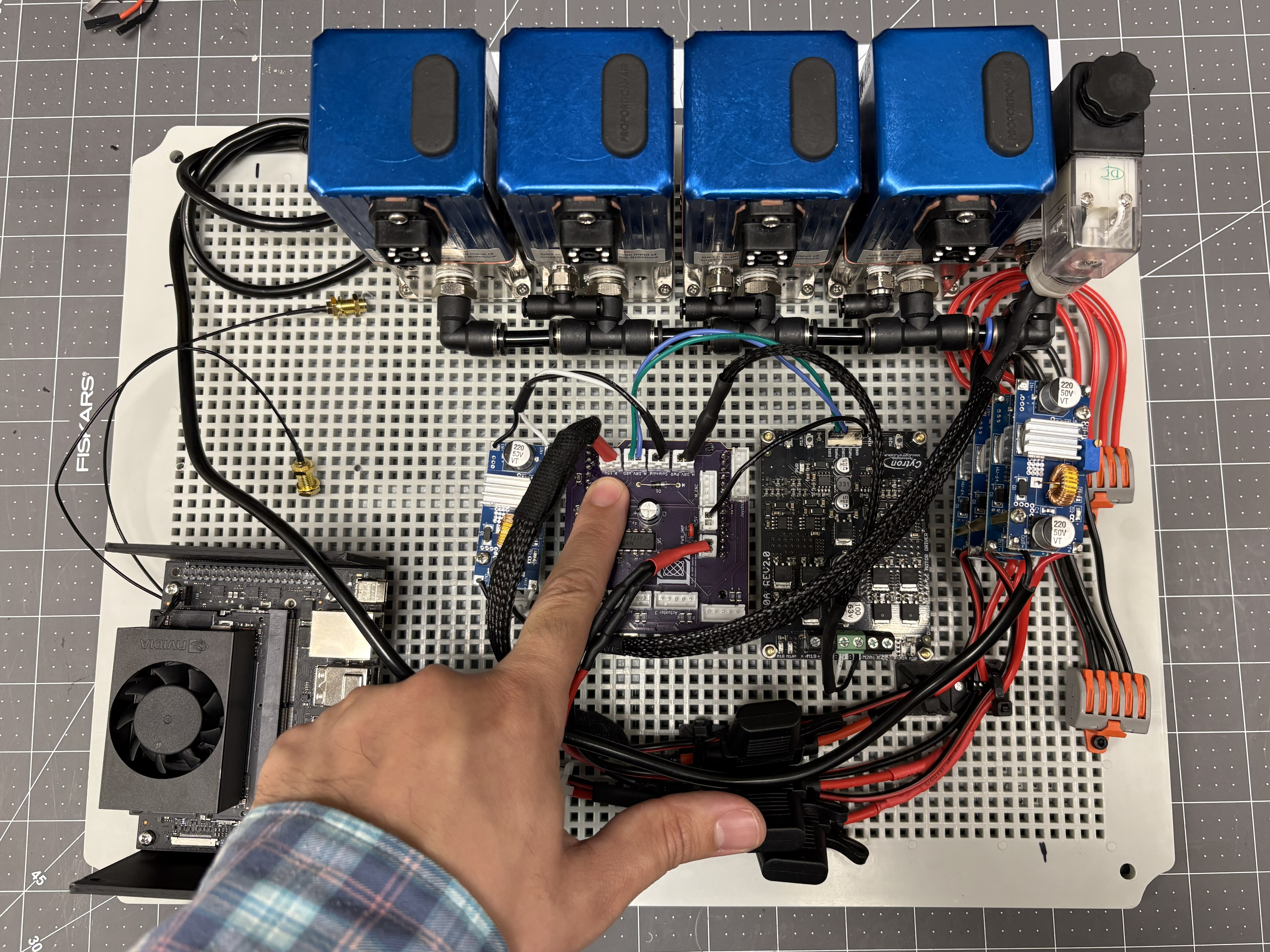
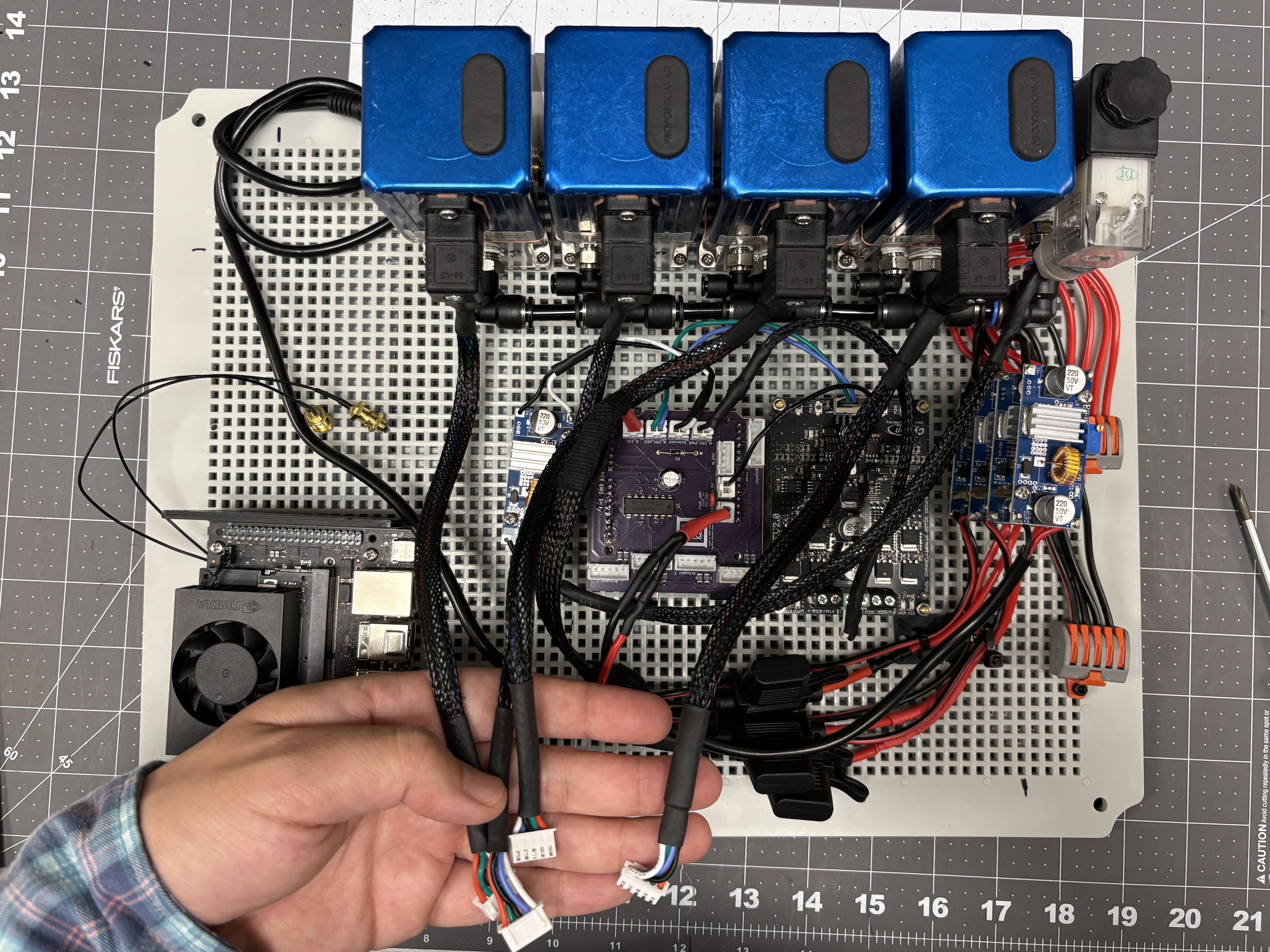
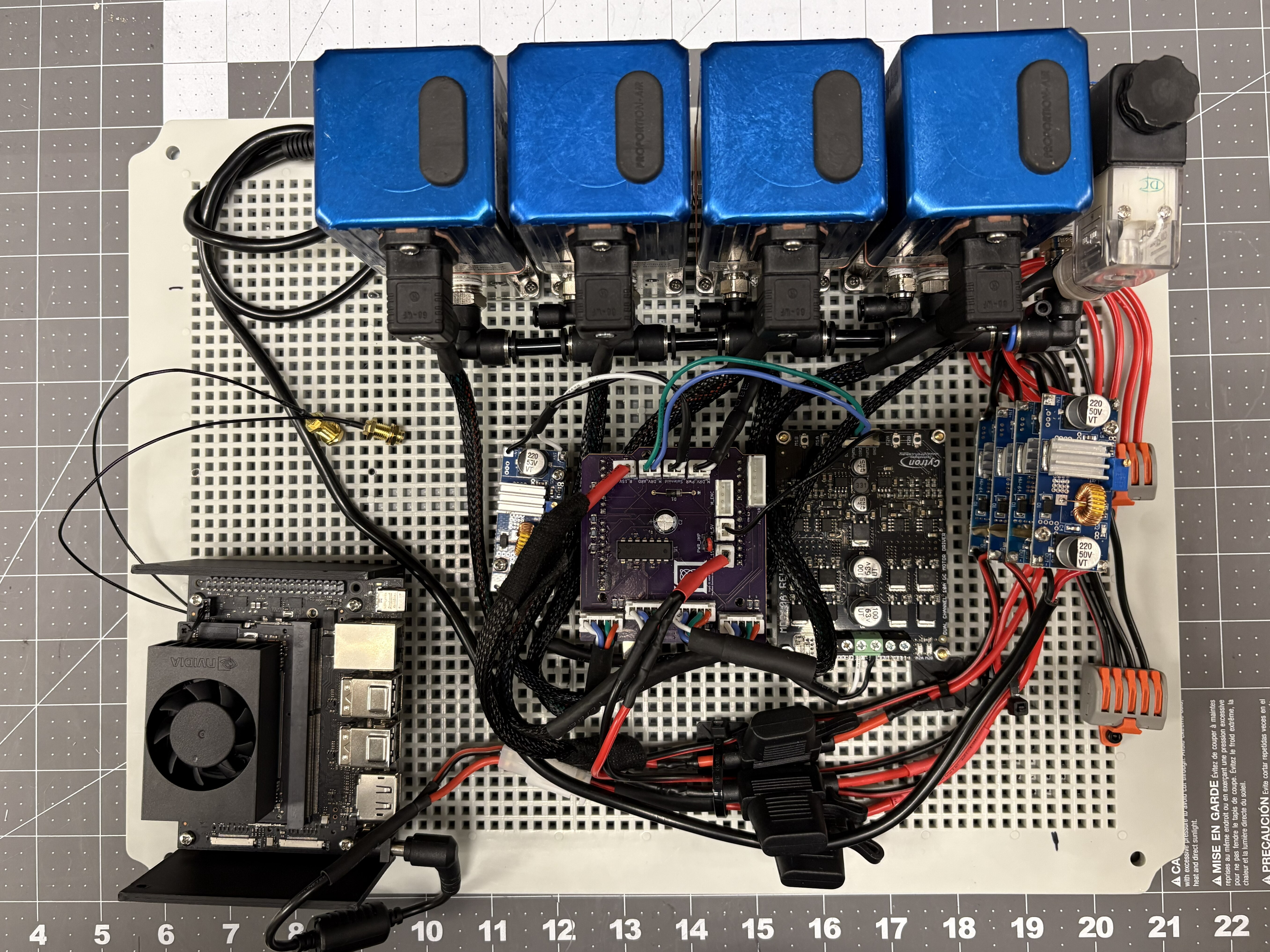
Connect the QB3 JST connectors to the Actuator 1, Actuator 2, Actuator 3, and Chamber ports in the arduino shield. In this case, Chamber is the leftmost QB3, followed by Actuator 3, Actuator 2, and Actuator 1.
-
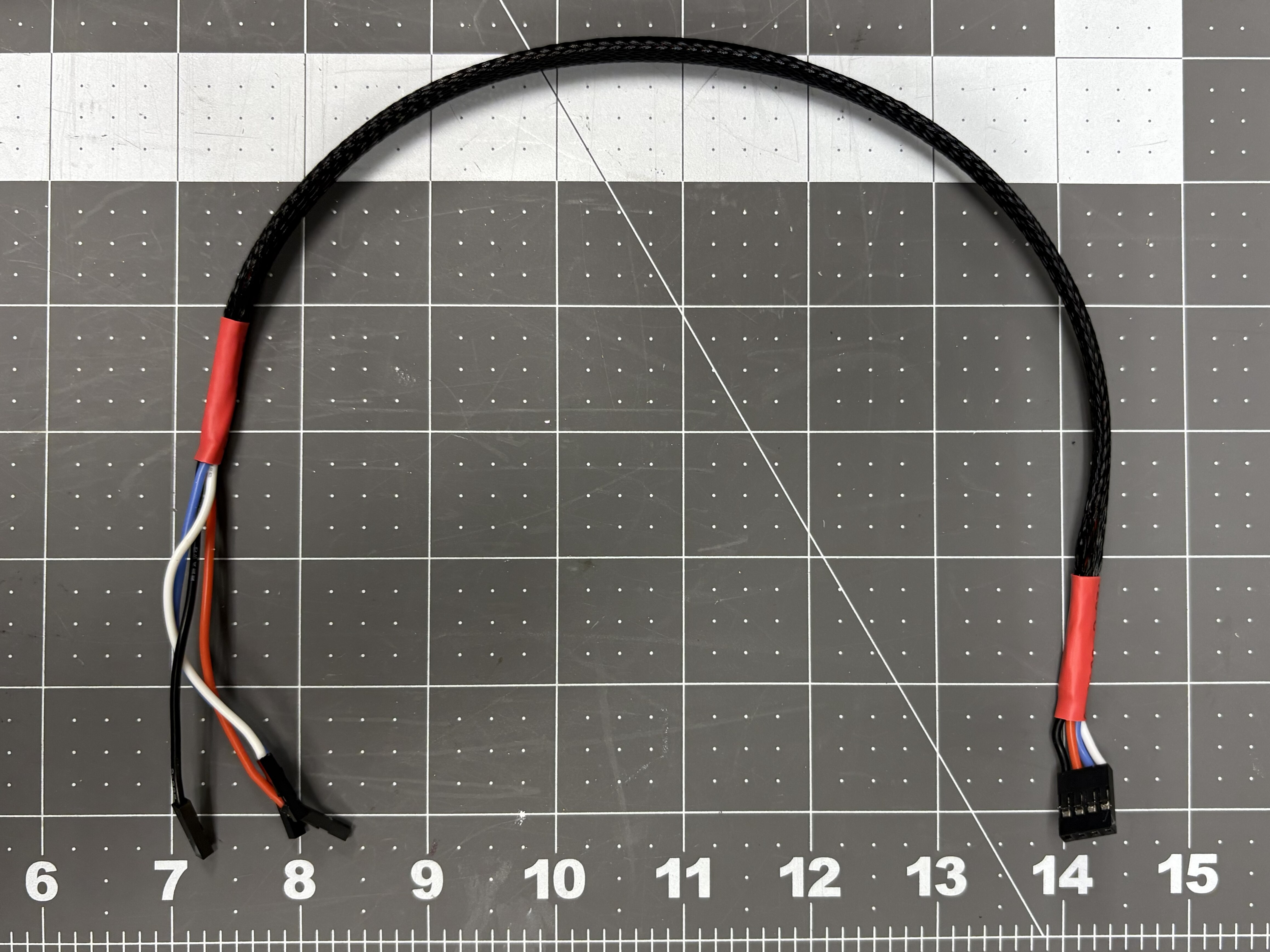
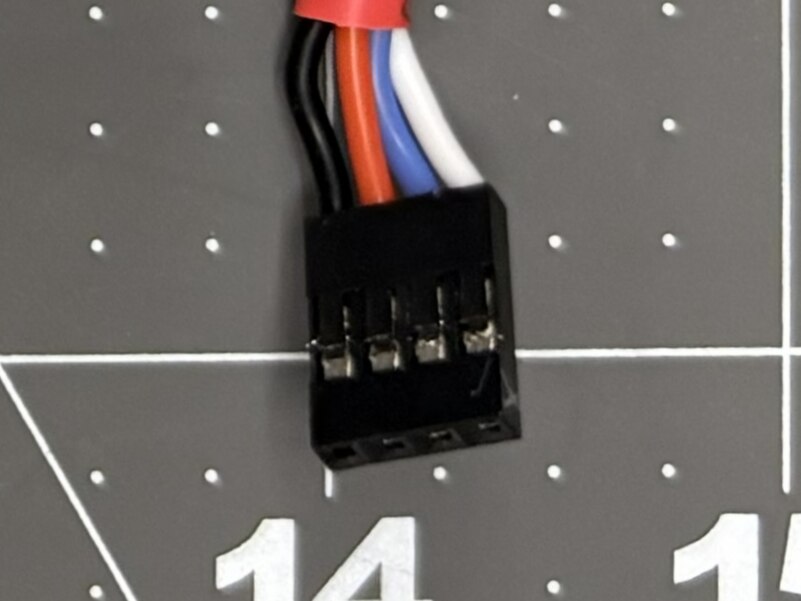
Make a connector with 4-22 AWG stranded wires, with 4-pin female Dupont connectors on one end. Make sure to follow the wire order shown in the picture below for this connector. Install individual 1-pin Dupont female connectors on the other end.
-
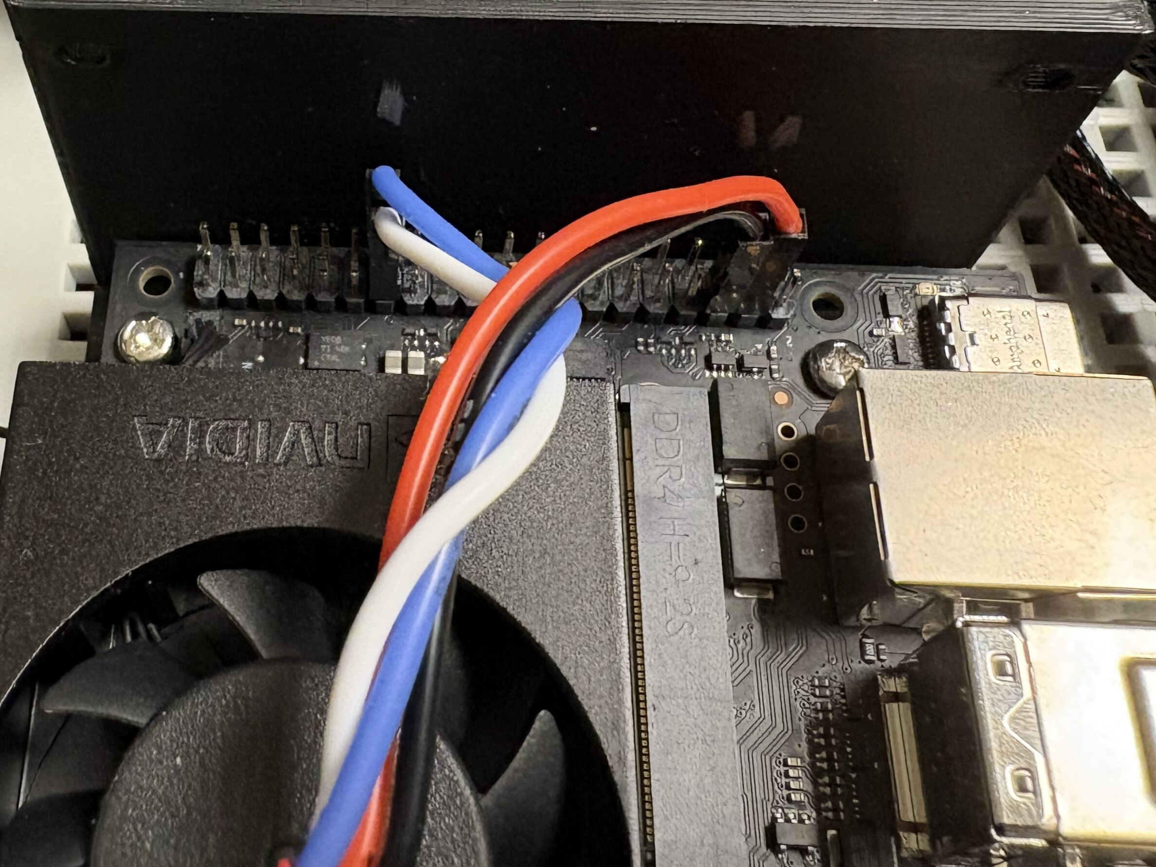
Connect the individual wires as shown. White is SCL, Blue is SCA, Red is 5.0V, Black is GND.
Return to Assembly → Step 5 to continue the build.